Tool/software:
Hi everyone!
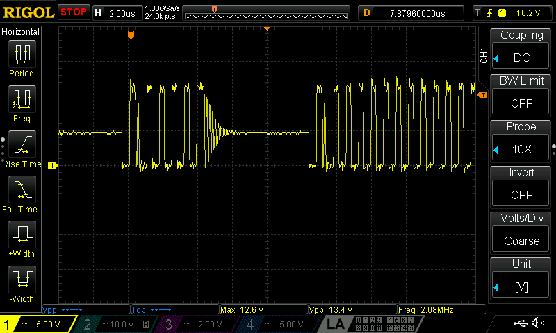
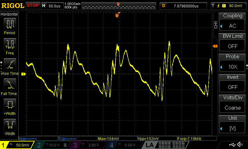
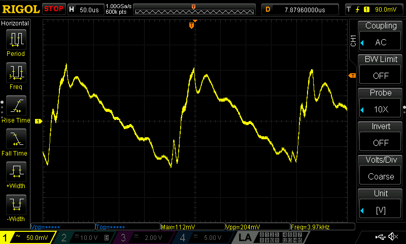
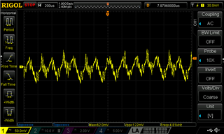
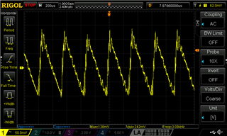
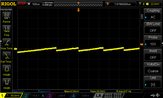
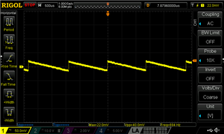
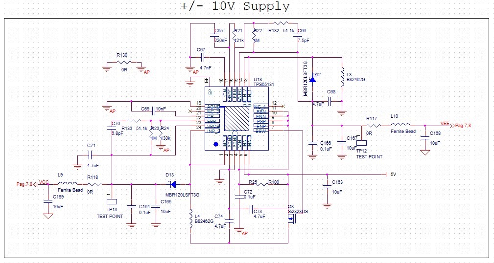
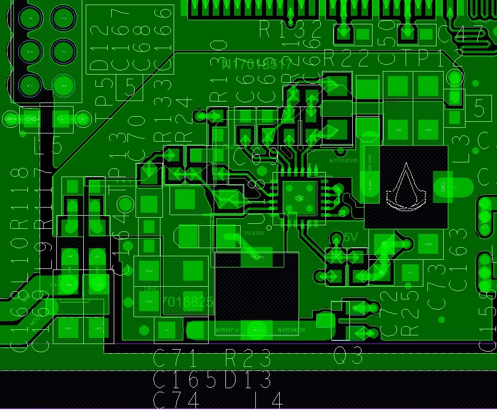
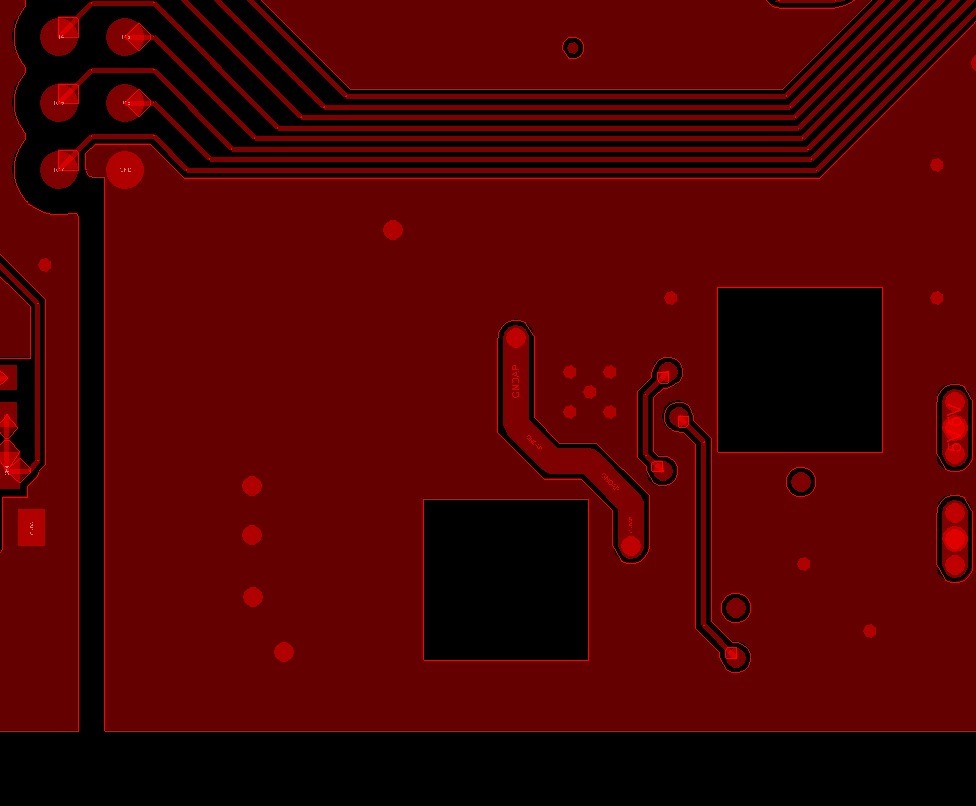
I used the TPS65131 in my project to have a dual power supply following the application notes and the routing of the evaluation board. When I power the board I hear an annoying buzz. I checked the schematic, PCB, power supplies and everything else but I didn't find any particular inconsistencies. If I put my finger on C70/R133 the noise fades a lot becoming almost imperceptible.
Any ideas on what it could be? Incorrect sizing? Incorrect routing? What tests can I do to understand where I'm going wrong? The integrated circuit seems to work correctly with the correct input and output voltages.
Below I post the electric diagram, the layout and the BOM.
Thanks to anyone who can help me.
| Item | Quantity | Reference | Description | Value | Manufacturer | PartNumber |
| ______________________________________________ | ||||||
| 1 | 1 | C65 | Multilayer Ceramic Capacitors MLCC - SMD/SMT 220 nF 6.3 VDC 220 nF 0603 X5R | 220nF | KYOCERA AVX | 06036D224KAT2A |
| 2 | 1 | C66 | Multilayer Ceramic Capacitors MLCC - SMD/SMT 7.5 pF 50 VDC 0.1 pF 0603 C0G (NP0) | 7.5pF | Murata | GRM1885C1H7R5BA01D |
| 3 | 1 | C67 | Condensatore ceramico multistrato MLCC, 0603 (1608M), 4.7nF, ±5%, 50V cc, SMD, C0G | 4.7nF | Murata | GRM1885C1H472JA01D |
| 4 | 2 | C68,C71 | COND CERAM SMD1206 4.7UF 50V 10% | 4.7uF | SAMSUNG | CL31B475KBHNNNE |
| 5 | 1 | C69 | CONDENSATORE MLCC 10nF ±10% 25Vdc C0G(NP0) SMD0603 | 10nF | KEMET | C0603X103K3GECTU |
| 6 | 1 | C70 | MLCC - SMD/SMT 0805 6,8PF 50VOLTS X7R 5% | 6.8pF | VISHAY | VJ0805A6R8BXACW1BC |
| 7 | 3 | C72,C164,C166 | COND CER SMD 0603 0.1UF 10% 16VOLTS | 0.1uF | MURATA | GRM188R71C104KA01D |
| 8 | 2 | C73,C74 | 4.7 µF, ceramic, 6.3 V, X5R | 4.7uF | AVX | 08056D475KAT2A |
| 9 | 5 | C163,C165,C167,C168,C169 | COND CERAM 10UF 25V 10% X7R SMD1206 | 10uF | AVX | 12063C106KAT2A |
| 10 | 2 | D12,D13 | Schottky Diodes & Rectifiers 1A 20V Low Vf | MBR120LSFT3G | onsemi | MBR120LSFT3G |
| 11 | 2 | L3,L4 | Power Inductors - SMD 4.7uH 2A 20% 6.3x6.3mm SMD | B82462G | EPCOS / TDK | B82462G4472M |
| 12 | 2 | L9,L10 | Perline di ferrite 400 mA 25 % IMP=1 kOhms Shielded SMD/SMT DCR=300 mOhms | Ferrite Bead | Pulse Electronics | BBGK00201209102Y00 |
| 13 | 1 | Q3 | MOSFET, P-channel, 12 V, 4 A, | Si2323DS | Vishay | Si2323DS |
| 14 | 1 | R21 | THICK FILM CHIP RESISTOR 121K 1% 0.1W 0603 SIZE | 121k | Vishay | CRCW0603121KFKEA |
| 15 | 2 | R22,R23 | SMD 1/4W 1M OHMS 0.05% 1206 10PPM | 1M | SUSUMU | RG3216N-1004-W-T1 |
| 16 | 1 | R24 | Thin Film Resistors - SMD RP 1J 0.166W 130K 0.1% 25PPM | 130k | TE Connectivity / Holsworthy | RP73PF1J130KBTDF |
| 17 | 1 | R25 | Resistore SMD Vishay Film sottile, 100O, 0603 (1608M), ±0.1%, 0.100W | R100 | YAGEO | RT0603BRC07100RL |
| 18 | 3 | R117,R118,R130 | RESISTORE FILM SPESSO 0R 5% 1/10W SMD0603 | 0R | Vishay Draloric | CR0603AJ/-000ELF |
| 19 | 2 | R132,R133 | THICK FILM CHIP RESISTOR 51.1K 1% 0.1W 0603 SIZE | 51.1k | Vishay | CRCW060351K1FKEA |
| 20 | 1 | U18 | x Dual, Positive and Negative Output DC-DC Converter | TPS65131 | Texas Instruments | TPS65131RGER |