This thread has been locked.

If you have a related question, please click the "Ask a related question" button in the top right corner. The newly created question will be automatically linked to this question.

LM51770: Bidirectional current operation does not work

Part Number: LM51770
Other Parts Discussed in Thread: LM5177

Tool/software:

Hi all, 

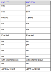
I am using LM51770 to drive a TEC device (sink and source current) using LM51770. Although, the ready PCB works nicely in boost mode and also in buck mode (where the LM51770 sources the current), but the sinking current mode does not work. Even if I appliy the proper control voltage, the device does not sink the current. Since, I could read at many places that LM51700 has current sink capability I believe that my design has an error but I could not figure out it. Could you help to point out the mistake in my design? 

Thanks in advance, 

Janos

8814.LM51770.pdf

  • Hi Janos,

    Thanks for using the E2E forum.

    I would recommend you to go through the attached app-note for LM51770 bidirectional current operation, and check the mentioned configurations which are required to enable the directional operation.

    https://www.ti.com/lit/an/snvaa80/snvaa80.pdf?ts=1751636828106&ref_url=https%253A%252F%252Fwww.ti.com%252Fproduct%252FLM51770

    Best Regards,

    Hassan 

  • Dear Hassan,
    Thank you for your reply.
    I've reviewed the app note and made some corrections to my PCB design, but I'm still encountering the same issue: the absence of reverse current.
    In the meantime, I purchased and tested the LM5177 evaluation module, which operates correctly with both forward and reverse current. I understand there's a difference between the LM5177 and the LM51770 I'm using.
    Could you please quickly check my configuration and identify any parameters that might be preventing reverse current?
    * **Mode pin:** 5V FPWM mode
    * **FB pin:** Resistive voltage divider from the output with a 1/24 ratio
    * **VIN voltage:** 12V fixed
    * **COMP:** 33pF in parallel with (15nF in series with 68K) to GND
    * **IMONOUT pin:** Floating
    * **SYNC:** Connected to 5V (fixed connection)
    * **CFG:** Shorted to GND (SCP Hiccup mode disabled, DRSS disabled)
    * **Output control voltage:** Connected to SS/ATRK (Analog Tracking used, voltage between 0-1V)
    Thank you for your time.
    Best regards,
    János
  • Hi Janos,

    Thanks for the information.

    I will come to you tomorrow.

    Best Regards,

    Hassan 

  • Hi Janos,

    Here are the differences between two devices.

    Here are some points you need to consider for reverse current operation for the LM51770 device.

    1. Mode needs to connect to VCC (FPWM mode)

    2. You need to apply higher output voltage compare to the set output voltage regulation (FB signal > FBref = 1V)

    3. The input voltage need to be higher than VDET threshold 3.4V and UVLO threshold 1.25V (Connect the UVLO pin directly to the Vin pin)

    4. SYNC pin need to connect to GND

    5. Negative Current limit enabled for the reverse current operation by changing the CFG settings ( Rcfg = 2.7kohms)

    6. In order to regulate the input voltage, you need to control the MODE pin as describe in the App note (page 5)

    For constant current and constant voltage charging using the reverse current operation you can see this appnote.

    https://www.ti.com/lit/ab/snvaa69a/snvaa69a.pdf?ts=1752231725154

    Best Regards,

    Hassan