This thread has been locked.

If you have a related question, please click the "Ask a related question" button in the top right corner. The newly created question will be automatically linked to this question.

BQ25622: USB Detection On BQ25622

Part Number: BQ25622
Other Parts Discussed in Thread: BQ25629

Tool/software:

Hello @TI team,

can you provide me USB detection algorithm on BQ25622 means when USB is plug in to charge battery i should know,for that give me algo ya resister uaed for it 
secondly give the algorithm for when my battery full charged .charging should stop.

give me algorithm ya resister list for both the cases. 


thanks.

  • Hi Ravi, 

    Please see my comments below.

    • VBUS_STAT in REG0x1E is the recommended register to check to determine whether USB source is present or not. VBUS_FLAG (REG0x21[0]) will be set to a 1b anytime VBUS status changes. 
    • CHG_STAT in REG0x1E is the recommended register to monitor for battery charging status. 

    We do not have sample algorithms created for these functions, but your I2C host will simply need to read from registers mentioned above to determine current status of battery charging and input source connection to charger IC. 

    Best Regards,

    Garrett 

  • hello @garrett ,thanks for your replay .

    can you guide me how can i know my battery is fully charged .can  we assume  when CHG_STAT =11b battery is fully charged.

  • Hi Ravi, 

    Yes when CHG_STAT changes from 10b 'Taper Charge' to 11b 'charge terminated' this indicates charge cycle is complete. 

    I will note CHG_STAT = 11b does also indicate 'Not Charging' status on this IC, but this will only be the status when charge is disabled via /CE pin pulled to logic high or EN_CHG bit set to 0b. 

    Best Regards,

    Garrett

  • hello   , i have some issue can you help me to resolve it.

    (1) what are the way(programming + hardware) for BQ25622 to achieved the faster charging tell me all in details, there is any role of ILIM pin and register related to it.

    (2) when my charging is disable (CE pin high and EN_CHAG =0 ) we read proper VBAT ADC value but when my charging is enable ( CE pin low and EN_CHAG=1) VBAT ADC value not read proper data ,read around VSYS while actual vbat is below it .

    (3) can we read ibat register when charging is disable because there is in datasheet mentioned "The IBAT ADC resets to zero when EN_CHG=0."

  • Hi Ravi, 

    Please see my comments below. 

    1) In general higher charge current will result in faster charging. Yes, ILIM pin plays a role in achieving fastest charging. Depending on resistor value at ILIM pin this can limit charge current. To achieve higher charge current I recommend the following in register configuration. 

    • First, set REG0x19[2] = 0b to disable input current limit set by ILIM pin.
    • Second, set REG0x06 to current rating of your input current supply or if input current rating is high enough you can set to 3.2A max. REG0x06 = 0xA00 will set to 3.2A. 
    • Third, set ICHG register (REG0x02) to desired charge current. 

    Other charging parameters, such as IPRECHG, ITERM, VREG, etc should be set based on the specs of the battery you are using in your system. 

    2) Please be aware the BQ25622 can only measure the battery voltage at BAT pin of charger IC. The difference in VBAT_ADC and hardware measurement of battery voltage during charging is most likely due to voltage drop across trace and wires between BQ25622 output and battery terminal. 

    3) With charge disabled, but BQ25622 operating in forward mode IBAT_ADC will always output a value of 0mA. Device needs to be in battery only or OTG mode for IBAT_ADC to measure battery discharge current. 

    Best Regards,

    Garrett 

  • hello   thanks for your replay,

    (1) we still have doubt why we cant read exact value of VBAT ADC when charging is enable as well as we cant get proper value of VBUS ADC (give constant supply 4.885v read value 4.664 when charging enable) , reading of both value proper when charging is disable.

    (2) for battery charging ,its take around 2 hour to charged the battery fully, when only charging is enable (CE pin is low and CHG_EN =1 set) what to do for achieving fast charger.


  • Hi Ravi, 

    Please see my comments below.

    1) Given your report that ADC reads proper value when charging is disabled it indicates the discrepancy is due to hardware setup in your testing. There is most likely IR drop due to parasitics between your input supply and the VBUS pin of the charger IC and similarly IR drop due to parasitics between BAT pin of charger IC and actual battery terminal.

    When no current is flowing due to charge disable there will be no voltage drop so it makes sense that ADC measurement matches your expectation, but as current increases the voltage drop will also increase. Please measure VBUS and BAT voltages as close to the BQ25622 device as possible, such as across input and output capacitors placed near BQ25622. When measuring near IC I expect your measurement to more closely match the ADC reading. 

    2) Faster charging can be achieved by increasing ICHG, as well as, increasing ITERM threshold. Now with this said it is recommended to use charge current and termination currents specified by the battery manufacturer. It may not be recommended to charge a specific battery at a higher current than you are currently testing with. 

    Best Regards,

    Garrett 

  • hello  ,


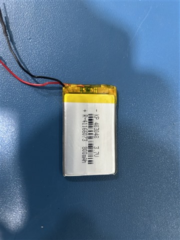
     attached my battery pic for battery specification.

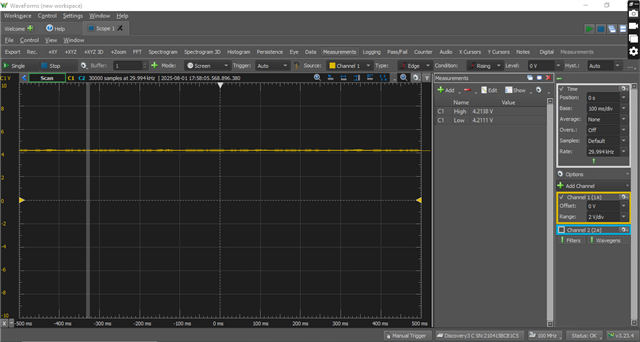
    (1) when my battery voltage read by multimer , reading =0.008v and when we try this battery to charging(CE low CHG_EN=0),at this time ADC value of VBAT read 4.226v constant through out the complete charging.

    (2) for the given battery in pic we charge it with logice given below.

    uint8_t reg_val_t = 0;

    reg_val_t &= ~(1 << 2);

    write_register(0x19, reg_val_t); // (function argue = register address,value)

    uint8_t buf=0xA0;

    write_register(0x06,buf);

    uint8_t reg_02=0;

    reg_02=(reg_02 & 0x3F) | (0x01 << 6);//3000mA

    // reg_02=(reg_02 & 0x3F) | (0x03 << 6); //2000mA

    uint8_t reg_03=0;

    // reg_03=(reg_03 & 0xF0) | (0x04); //2000mA

    reg_03=(reg_03 & 0xF0) | (0x09); //3000mA

    write_register(0X02, reg_02);

    vTaskDelay(pdMS_TO_TICKS(100));

    write_register(0X03, reg_03);

    here we try to set REG0x19[2] = 0 ,set REG0x06= = 0xA0 and i want set 3000mA in (REG0x02).

    problem is battery charged fastly(15 min) upto 3.8v then to reach 4.2v take 1.5 hour

  • Hi Ravi, 

    Please see my comments below. 

    1) Your observation leads me to believe some form of battery protection has been triggered, such as an over-discharge protection. Often battery protection ICs will disconnect battery from charger and in this case BQ25622 measured BAT pin connection as open and it will very quickly charge the output capacitor up to 4.2V VREG setting. I recommend you check what is required method to close battery protection IC to allow the battery to charge as expected. 

    If battery voltage was in fact 0.008V BQ25622 would start charge from trickle charge phase rather than quickly charge up BAT pin output to 4.2V. 

    2) To set 3000mA ICHG you will need to set 16-bit REG0x02 = 0x980. Put another way this would be 8-bit REG0x02 = 0x80 and REG0x03 = 0x09. Regarding charge cycle firstly, for your information it is expected that the CV phase of charge can take a long time relative to the CC phase of charge depending on configuration of charging parameters. 

    With that said, you can also expect shorter charge time with a more optimized hardware setup. Large IR drop across path from BAT pin to actual battery terminal will result in early entry to CV phase and cause longer charge time. Please check 'CHG_STAT" bits in REG0x1E when your battery reaches 3.8V to confirm whether device is entering CV phase at this time. For example, using shorter wires between BQ25622 and the battery cell should result in shorter charge time. 

    Best Regards,

    Garrett 

  • hello  ;

    (1) We do not understand what over-discharge protection means in the context of VBAT ADC readings. Our requirement is to read the VBAT ADC value while the battery is charging. However, we are consistently getting a constant 4.2 V reading throughout the entire charging process.

    Does over-discharge protection need to be disabled in order to get accurate VBAT readings during charging?
    If yes, please guide us with the exact steps to disable over-discharge protection.

    (2) Our battery still takes around 2 hours to fully charge.
    We are using VBUS = 5 V, IBUS = 470 mA, and VBAT initially = 0.005 V.
    The IBAT reaches a peak of 1 A at the start and then gradually decreases.
    The charging mode remains in taper charge (Constant Voltage or CV mode) throughout.

    here we set the ICHAG limit to 3A(REG0x02 = 0x80 and REG0x03 = 0x09.)

    • The battery charges from 0 V to 3.8 V in just 15 minutes.

    • However, it takes 1.5 hours to charge from 3.8 V to 4.1 V.

    We want to minimize this 1.5-hour duration as much as possible.
    Please guide us on how to reduce this taper charging time efficiently.

  • Hi Ravi, 

    1)The comments on battery over discharge protection were specifically related to your observation of VBAT_ADC = ~4.2V while measured battery voltage was 0.008V. This would be a protection within your battery pack as typically Li-Ion batteries are not allowed to discharge all the way to 0V. Do you have a plot of battery voltage throughout your charging? Have you verified what voltage is observed at BAT pin of BQ25622 during charging rather than rely solely on the VBAT_ADC. 

    However, we are consistently getting a constant 4.2 V reading throughout the entire charging process.

    This is not expected behavior. Especially when in precharge phase of charge you should not see such a voltage delta between BAT pin and actual battery terminal. 

    2) I will reiterate my previous point that you need to improve your hardware setup so that you do not enter CV mode too early. In an ideal scenario CV mode should not be entered until battery voltage reaches your desired full charge voltage (4.1V based on your response). Device is in CV mode of charge based on voltage measured at BAT pin. Please measure voltage at BAT pin of BQ25622 during the 15 minutes to charge up to 3.8V. Is this voltage reaching 4.2V? 

    Best Regards,

    Garrett

  • hello  ,

    (1) I attached my VBAT plot during charging. It taken initially and remains constant throughout the charging process. However, I believe the battery voltage should gradually increase, which I want to monitor using the ADC.

    Please guide us step by step how to read ADC for VBAT.

    2) We are still facing the issue of long charging time. The battery takes around 2 hours to fully charge, and the charging mode remains in taper (CV mode) throughout the process.

    Based on your suggestion:

    "Please measure the voltage at the BAT pin of the BQ25622 during the first 15 minutes of charging. Does the battery voltage reach 4.2V?"

    We performed this test and confirmed that the voltage does not reach 4.2V during the first 15 minutes. The battery voltage (measured after removing the battery and using a multimeter) reaches around 3.8V, and after that, IBAT gradually decreases. During the 0V to 3.8V phase, IBAT drops quickly, but from 3.8V to 4.1V, the current decreases very slowly, resulting in a long charging duration.

     Please guide us with step-by-step instructions to achieve fast charging using the BQ25622. We aim to reduce the time taken to reach full charge (4.2V) while keeping the battery safe.

    NOTE : our hardware setput set proper and fully tested ,

  • Hi Ravi, 

    1) Yes battery voltage is expected to gradually increase. Do you have a capture which shows VBAT at same time input supply is connected/turned on? Also where are you measuring VBAT from in the plot? 

    The ADC is turned on via bit 7 in REG0x26. Then to read VBAT_ADC output you simply need to read from REG0x30 then REG0x31. These two 8-bit registers combined output the VBAT ADC measurement. 

    2) Please measure the voltage near the charger IC BAT pin with the battery still attached instead of measuring at the battery after removing it from the charging system. I am trying to understand the voltage difference between the charger IC output and the battery. By measuring the disconnected battery we do not know this difference. 

     Please guide us with step-by-step instructions to achieve fast charging using the BQ25622.

    The device performs the charge cycle automatically. There is no step by step instructions besides proper configuration of charging parameters and optimizing hardware setup.

    Best Regards,

    Garrett 

  • hello  ,

    Let me explain my code flow:

    1. First, I enable charging by pulling the CE pin low and setting EN_CHG = 1 by writing 0x20 to Register 0x16.

    2. Then, I set REG0x19[2] = 0b0 to disable the input current limit set by the ILIM pin.

    3. Next, I set REG0x06 = 0xA0 to configure the input current limit to 3.2A.

    4. I set REG0x02 = 0x98 and REG0x03 = 0x09 to configure the charge current to 3A.

    5. Then, I run ADC read functions to measure VBAT, IBAT, VBUS, IBUS, and VSYS.

    Observations:

    • After loading the code onto the PCB without connecting the battery:

      • VBUS = 5V

      • IBUS = 0.03A

    • When the battery is connected (initial voltage = 3V):

      • VBUS drops to 4.7V

      • IBUS increases to 0.85A

    Problem:

    • The battery voltage quickly rises from 3V to 3.8V within 12–15 minutes.

    • At this time, REG0x1E bit[1:0] = 01, indicating Trickle Charge, Pre-charge, or Fast Charge (CC mode).

    • However, after reaching 3.8V, the charger switches to CV (Constant Voltage) mode, and it takes around 1.2 hours to reach 4.1V.

    BATTERY PIC IS BELOW WHICH I USED.

  • Hi Ravi, 

    Thank you for your response. Please see my comments below. 

    For your software procedure in step 4 please set REG0x02 = 0x80. Writing 0x98 is setting 2 reserved bits and it is not recommended to be writing to reserved bits. Beyond this comment I have no concerns regarding your software flow. 

    When the battery is connected (initial voltage = 3V):

    • VBUS drops to 4.7V

    • IBUS increases to 0.85A

    Do you observe ICHG reach 3A setting during the initial 12-15 minutes charging to 3.8V? If not I recommend reading from REG0x1D during this portion of charge to check if device is in DPM (dynamic power management) status. This question can also be ignored if charge current is expected to be lower than 3A due to current capacity of your input source used in the test. 

    However, after reaching 3.8V, the charger switches to CV (Constant Voltage) mode, and it takes around 1.2 hours to reach 4.1V.

    This observation indicates BQ25622 is measuring VREG voltage setting at BAT pin. Your charge time will be reduced if you can reach CV mode of charge at a higher battery voltage, but this will require you to reduce the parasitic resistance along the path from BAT pin of charger IC to the battery terminal. 

    Overall charge time is reduced by remaining in CC mode charging for longer before transitioning to CV mode. 

    Best Regards,

    Garrett 

  • hello  ,

    Let me clarify that all parameter values mentioned in the above reply and in this replay are actual values measured using a multimeter and not ADC values from the code.

     Case 1:

    • Without connecting the battery:

      • VBUS = 5V

      • IBUS = 0.03A

      • (VBUS is supplied by a regulated DC power supply set to 5V and 1A)

      • Initial battery voltage = 3V (measured via multimeter)

    • After connecting the battery:

      • VBUS = 4.7V

      • IBUS = 0.85A (observed on the applet display)

      • Charging takes the battery from 3V to 3.8V in 15 minutes

      • Charging mode from REG0x1E bit[1:0] = 01 (Trickle, Pre-charge, or Fast Charge (CC mode))

      • Then it takes 1.2 hours to charge from 3.8V to 4.1V in CV mode

    • VINDPM was active during 3V to 3.8V, and not active after 3.8V to 4.1V.

     Case 2 (Experiment):

    • A 6.3Ω load was connected.

    • Without battery:

      • VBUS = 5V

      • IBUS = 0.45A

      • (VBUS from regulated DC power supply, set to 5V and 1A)

    • After connecting the battery:

      • Battery voltage = 3V (measured via multimeter before connection)

      • VBUS = 5.8V

      • IBUS = 1.02A

      • Load (6.3Ω resistor) draws ≈ 0.504A

      • Battery charges from 3V to 4V in CC mode (REG0x1E bit[1:0] = 01)

      • Then transitions to CV mode

    • VINDPM is active in this case as well.

     Case 3:

    • Power supply settings:

      • V = 5V, I = 2.3A

      • 6.3Ω load is still connected

    • Charging starts directly in CV mode

    • VINDPM is not active

     Goal:

    We want to minimize the charging time as much as possible. Please guide us on how to achieve this.

     Second Issue:

    What is the best charging mode (CV or CC)?
    How can we achieve and maintain it accurately?

  • Hi Ravi, 

    Please see my comments below. 

    What is the best charging mode (CV or CC)?

    Please refer to the battery charging profile (Figure 8-2) in the BQ25622 datasheet. Both CC and CV mode are part of the standard charge profile for a Li type battery. The device charges in CC mode then CV mode once battery voltage reaches full charge regulation voltage. Neither mode is considered better than the other. 

    BQ25622 does not have remote battery voltage sensing, so it only is able to measure battery voltage at BAT pin of charger IC. If there is significant parasitic resistance between BAT pin and battery, such as across small gauge wires shown in your battery image, the BQ25622 will reach CV phase earlier in charge cycle and this will result in a longer overall charge time. Voltage drop due to parasites resistance will be more impactful at higher charge currents. 

    Optimization of your hardware setup is the recommended method to achieve faster charge time while still charging your battery in a safe manner. 

    How can we achieve and maintain it accurately?

    BQ25622 will automatically transition from CC to CV based on measured battery voltage and the accuracy of VREG regulation is listed in electrical characteristics table. 

    Best Regards,

    Garrett

  • HELLO  ,

    We have paused debugging the previously mentioned issue for now.

    Currently, we are facing a new issue: we are trying to run our PCB on battery power only, but the VSYS pin is not receiving sufficient current, which causes the system to reset.

    How can we ensure a continuous current supply from VBAT to VSYS? Please guide us.

  • Hi Ravi, 

    How can we ensure a continuous current supply from VBAT to VSYS? Please guide us.

    With default register configuration the BQ25622 will allow battery to power SYS automatically. The battery discharge overcurrent threshold is 6A (Ibatfet_ocp) and and the battery undervoltage lockout protection falling threshold is typical 2.2V (Vbat_UVLO). 

    What is the expected system current draw in your system? Have you measured SYS voltage right before your system resets? 

    If the BQ25622 is the cause the battery overcurrent or battery undervoltage protection is most likely what is causing the system to reset. Please be aware the battery pack itself may also have its own overcurrent or undervoltage protection that is triggering in your testing. 

    Best Regards,

    Garrett

  • Hello  ,
    (1) voltage just before our system reset is 1.8v
    (2) our system draw 1A current.
    (3) BATFET_CTRL bit of REG0x18 is 00.
    (4) vsys fault flag is set to 0.
    (5) vbat  fault flag is set to 0.

    we need proper solution for this.

  • Hi Ravi, 

    Thank you for your response. 

    Please refer to Section 8.3.10.1.1 'Battery Undervoltage Lockout' in the datasheet. It is expected behavior for BATFET connecting BAT to SYS to turn off when VBAT falls below Vbat_uvlo threshold. 

    Your report of system voltage = 1.8V confirms the battery voltage is low and approaching this undervoltage threshold. Its purpose is to prevent battery overdischarge. If in reality your battery voltage is much higher than the threshold I recommend you check your hardware setup to determine amount of voltage drop from battery terminal to SYS when drawing 1A. 

    Additionally, BAT_UVLO falling threshold can be lowered from typical 2.2V to 1.8V by setting REG0x19[5] = 1b. 

    Best Regards,

    Garrett 

  • hello  ,
    here our vbat not changed when system reset its constant 3.9v , our vsys changed 1.8v just before reset.
    we set REG0x19[5] = 1b.  but not improvement 

    please guide us with proper solution

  • Hi Ravi,

    Can you please provide a waveform of VSYS voltage, VBAT voltage (voltage measured at the BQ25629 BAT Pin), and VCELL voltage (voltage measured at battery cell in your battery pack) when the load to SYS is applied? Preferably with the 3 waveforms in the same capture?

    As Garret mentioned, a likely cause for this behavior and the previous behavior is high resistance between the BQ25629 BAT pin (VBAT_BQ) and the battery cell (VBAT_CELL). A high resistance will cause a voltage drop that is proportional to the current (VBAT_BQ - VBAT_CELL = IBAT * Resistance). So during charging (Positive IBAT) at high current VBAT_BQ > VBAT_CELL. During discharging (Negative IBAT) VBAT_BQ < VBAT_CELL. So even if VBAT_CELL is measured at 3.9V, it is possible that VBAT_BQ is at a lower voltage.

    The BQ25629 only monitors VBAT_BQ and can't monitor VBAT_CELL, so we recommend reducing the resistance between the two nodes as much as possible. This includes designing with wider PCB gauges and using larger gauge wires.

    Best Regards,

    Juan Ospina

  • hello  ,

    Can you please guide me on how to measure the battery level during charging? The VBAT ADC shows the voltage at the battery pin, which is not the actual battery voltage  during charging. Please provide a method to measure battery level while charging.

  • Hi Ravi,

    Since the difference between voltage at the battery pin vs actual battery voltage is cause due to the voltage drop due to resistance between those two points (I_battery * R_trace), the most recommended method for measurement is to minimize or eliminate charge current and discharge current for the period of time during the ADC read.

    Minimizing I_battery by pausing charging and pausing components with a heavy current load should reduce the difference between V_BAT and V_CELL read by the VBAT ADC. Additionally, minimizing R_trace in your design by widening traces and minimizing the distance between the pin and the actual battery may help in this performance as well.

    Best Regards,

    Juan Ospina