This thread has been locked.

If you have a related question, please click the "Ask a related question" button in the top right corner. The newly created question will be automatically linked to this question.

TPS544B20: Not able to provide stable 1V to the load

Part Number: TPS544B20


Tool/software:

Hi

I have attached the schematic of the IC. 

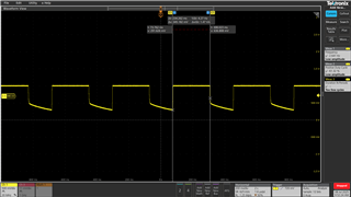
When the load is in reset, it is able to generate 1V but as soon as load comes out of reset the output voltage keeps fluctuating and not stabilizing at 1V. 

My load is taking 4A of current. 

Layout seems to be same as suggested in the datasheet.

Kindly give suggestions to solve the problem.

  •  

    Can you share the waveforms of what you are seeing?

    The schematic appears to show 3x 100μF ceramic capacitors + 2x 470μF polymer capacitors. 

    Can you share the details of the 470μF capacitors?

    Are there any other capacitors on this 1V rail?  Possibly at the load side?

    The 1,240μF of output capacitance is likely more than the internal D-CAP2 loop can handle without some additional support.

    Without a feedforward capacitor (C2365 in your schematic) the D-CAP2 control loop produces an output impedance of Vout/Vref x L/tau where tau is the time-constant of the internal ramp, set by the switching frequency and given in table 11 of the datasheet (https://www.ti.com/lit/ds/symlink/tps544b20.pdf#page=55

    with a 0.56μH inductor, that comes to 12.2mΩ

    With 1,240μF of output capacitance, that drives a loop bandwidth of about 10kHz.  The low loop bandwidth could be a cause of the loop's instability.  this would be even more likely if there is additional capacitance on the 1V output.

    Some options to try:

    1) Remove one (or even both) of the 470μF polymer capacitors.  For a 4A load current, you likely don't need this much capacitance.  The expected overshoot on a 4A load drop is only 30mV with just 3x 100μF of output capacitance.  That will push the loop bandwidth out to 43kHz, still very conservative, but more stable than 10kHz. 

    2) Populate the feedforward resistor (C2365).  This can also increase the loop bandwidth, though not as strongly as reducing the output capacitor, since it is limited be the Vout/Vfb ratio of 1V / 0.6V (1.67x) but that might be sufficient to stabilize the loop.  The high-pass crossover frequency of C2365 with R1448 (20k) should be the expected crossover without the feedforward.  With the 3x 100μF + 2x 470μF and 20k resistor, that would be 1 / ( 2 x Pi x 20k x 10.2k) or 780pF.  I would recommend selecting 820pF.

    If you want to reduce Cout by removing the polymer capacitors and add the feedforward, that would be 180pF.

  • hii

    1) Waveforms of the output attached.

    2) Details of 470uF caps are as follows

    vendor part no - PCG0E472MCL1GS(4700 µF 2.5 V Aluminum - Polymer Capacitors Radial, Can - SMD 10mOhm 2000 Hrs @ 105°C)

    3) Snapshot of the caps on load is attached and their details are as follows

    a) 100uf vendor part no - 12106D107MAT2A(100 µF ±20% 6.3V Ceramic Capacitor X5R 1210 (3225 Metric)

     b) 1uf vendor part no - 0402YD105KAT2A(1 µF ±10% 16V Ceramic Capacitor X5R 0402 (1005 Metric))

    c) 01uf vendor par no - KGM05AR71C104KH(0.1 µF ±10% 16V Ceramic Capacitor X7R 0402 (1005 Metric))

    I will try the options you have suggested and let you know the outcome.

    Thanks

  •  

    Thank you for sharing.  The waveforms do not appear to show output instability, at least at the 200ms/division scale, though it is possible there is a higher frequency instability (oscillation) in the output voltage that is not visible at this scale.

    It looks like the output is running for 230ms, then shutting down for about 100ms before restarting.  That is an unusually long restart delay for the TPS544B20.  Faults (Over Current, Over Voltage or Under Voltage) generally trigger a 7x the TON_RISE setting delay prior to restart, which defaults to 3ms without PMBus programming.  

    One note on the schematic, you have CNTRL pulled up to VIN (12V) the maximum voltage on the CNTRL pin is 7V.  You should add a CNTRL to GND resistor to avoid pulling CNTRL up to 12V.  You could populate R1446 (to 3V3) to limit the pull-up, assuming 3V3 can sink current.  A resistor of 2.4kΩ or less would limit the CNTRL voltage to less than 5V and prevent it from being pulled up above 7V.

    It looks like your added capacitance has an additional 6x 100μF, which is bringing the total capacitance above 1,900μF, which would definitely bring the loop stability into question.  If that is indeed the issue, you should seen an oscillation in the output voltage when observing the output voltage at 10μs/division.  This might not be observable at 200ms/division.  But I would not expect a 100ms time-out to result.

    Given the time-out period, I would recommend looking at the CNTRL voltage, and the EN_1VD_MPL signal driving it.

  • Hi,

    I have disconnected CNTL pin from 12V by unmounting R1458 and connected it with 3.3V by mounting R1446 = 10K. This got me constant 3.1V at CNTL pin which is above the required threshold to switch ON the module but nothing has changed. I am still getting the same output waveforms as before.

    I'm having trouble understanding why the supply is consistently switching off its output and then turning back on. Please help me identify the cause of this issue.

  •  

    1) can you please provide a couple of output voltage waveform at 10μs per division.

    One showing the output voltage while it's running for the 230ms

    For this, adjust vertical scale to 50mV/division and the 1V reference level to 1 division below the top of the display (+3 divisions)

    Set the trigger level for 1V

    Set the trigger position to the middle of the screen

    One showing the last 80μs before the out drops. 

    For this, leave the vertical scale, but reduce the trigger level 950mV so it only triggers when the output shuts off

    Move the trigger position to the right, 2 divisions in from the right edge of the screen (3 divisions right of center) 

    That should help us see what is happening in order to determine a likely cause.

    3) Can you record VIN and CNTRL with an oscilloscope so we can confirm if they are dropping out?

    4) It looks like you have the PMBus CLK and DAT pins connected, are you able to talk to the device over PMBus and read the STATUS commands?  If there is a fault occurring, the STATUS commands will indicate the source of the fault.

  • Hi,

    I've read the device using PMBus and have read the STATUS_BYTE (78h) register, which is toggling between 46h and 06h. This indicates a temperature-related fault. Going further, I read the STATUS_TEMPERATURE (7Dh) register and found its value to be C0h, suggesting both OT Fault and OT Warning have occurred. Could you please help me understand the possible causes of these temperature-related faults?

    I have not yet taken the output voltage measurements as you suggested. Pl let me know if you still need them.

  •  

    The TPS544B20 senses temperature using an external, diode connected (Collector and Base shorted) bipolar junction transistor and the differential in that BJT's forward drop between a 10μA current and a 100μA current pulsed on the BJT. 

    This is Q28 in your circuit.

    Check the connection to Q28, and the return ground to AGND.

    You can short out Q28 Collector to Emitter to disable temperature sensing and confirm that is the issue shutting down the converter.

  • Hi, I've made a breakthrough in troubleshooting the issue. By unmounting C594 and shorting the collector and emitter pads of Q28, I've confirmed that the temperature sensing circuit was causing the converter to shut down. With this modification, the output is now stable at 1V. I'd like to thank you for guiding me to this point. Next, I'd appreciate your help in understanding potential issues with the schematic, IC, or layout that might be causing incorrect temperature sensing. What could be the possible causes for this malfunction?

  •   

    Great, that explains a lot. 

    As I explained, the TPS544B20's temperature sensing function senses the change in forward voltage drop for the 2N3904 BJT between a 10μA and 100μA current imposed on the BJT.  It can be sensitive to added resistance, which increases the change in sensed voltage, noise coupling, which is rectified due to the BJT's I-V curve, and capacitance.

    1) Make sure a 2N3904 BJT is used, and it has not been substituded with a different BJT that might have a different ΔVbe versus temperature relation ship.

    2) Try changing the capacitor from 1000pF to 330pF

    3) If the BJT is located away from the TPS544B20, try moving the 330pF capacitor close to the TPS544B20 to reduce noise. 

    4) Check the layout for any switching signals, especially the Boot pin connections or switching node, or even the AGND connection to AGNDSNS, which could couple into the sense connections to the BJT