This thread has been locked.

If you have a related question, please click the "Ask a related question" button in the top right corner. The newly created question will be automatically linked to this question.

UCC28070: Current transformer placement in series with inductor or MOSFET

Part Number: UCC28070
Other Parts Discussed in Thread: TIDA-00130

Tool/software:

Hi team, 

Our customer, ESAB, had questions about the placement of the current transformer while implementing the PFC driver. 

The two configurations are below:

1. Current transformer connected in series with the MOSFET (between the MOSFET and Inductor-Diode node) : Current sensing only during the MOSFET ON condition

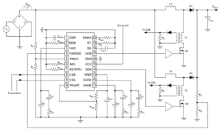
2. Current transformer connected in series with the inductor (between inductor and MOSFET-Diode node): Current sensing when MOSFET is ON & OFF

The questions are as follows:

  1. What are the differences in PFC operation between the two configurations? This is a high power application, ~10kW
  2. What is the recommended configuration using the UCC28070? (I assume the first configuration, given it is the one in the datasheet, but I would like to confirm)
  3. What are the effects/benefits of using the second configuration?

Also, if there are any clarifying questions you need answered, please let me know and I'd be happy to get back to the customer. Thank you.

Best,

Julius Burtell

  • The config 2 image is not clear. Can you show the full schematic?

  • Hi Ning,

    Please see the attached PDF for the config 2 schematic. It is an output of Webench.

    4263.WBDesign24.pdf

  • Julius,

    If you check the schematic on the right, you will see a diode that block the voltage when the FET is OFF. Essentially, option 1 and 2 are the same. 

    In reality, option 2 can save you a dedicated transformer as the sensing winding is coupled with the main inductor, but it may also limit the main inductor selections.

  • Hi Ning,

    Thanks for the help. Our customer still has a few questions regarding the PFC configuration. 

    For added context, they are using the following SiC module: 

    With this module, they cannot connect the transformer as described in the datasheet (configuration 1). They are instead looking to use the second configuration, as they can place the inductor/transformer on the node between D2 and the FET. 

    There is still concern that the CSx inputs would see current in both the FET on and off time using configuration 2. Would you be able to clarify which direction the current is going, and how the diode "Dra" in the second configuration is blocking the voltage when the FET is off? The customer is concerned that the current direction will be the same no matter if the FET is on or off, so that would mean a sensed current on the CSx inputs. 

    Thanks for the help!

    Best,
    Julius

  • Dra pairs with Zcda. I don't think it will work if they feed the common source current to two different phases.

    Can they use two modules, one for each phase?

  • Hello Julius, 

    I'm sorry, but I have to disagree with Ning on the current sense configuration question.  
    Configuration 1 as shown in the datasheet is the proper way to sense the two separate phase currents for the UCC28070 controller.
    Config 2 will not work, because there is continuous DC current (with ripple) in the current transformer and there is no off time in which to reset the magnetizing current that builds up in the magnetizing inductance.  It will saturate.  The CT cannot be considered to be part of the main boost inductor, and cannot be placed in series with the boost inductor unless some special reset circuit can be designed to forcibly overcome the boost current to reset the core. 
    I don't think that this can be easily done, or else everyone would be doing it and we wouldn't need the current synthesis feature in the controller. 

    There is something wrong in the Webench program that resulted in the incorrect configuration shown.  Furthermore, the polarity of the CT in the Webench is also wrong.  These issues will have to be corrected by our Webench team. 

    Meanwhile, I do agree with Ning that using a common-source SiC module will also not work because it does not allow independent sensing of source currents.  If a module can be found with separate source pins for each SiC FEt, or two single Sic modules can be used, then the phase currents can be independently sensed using source resistors and gained-up with op-amps to keep power dissipation low.  
    (Ref TIDA-00130: https://www.ti.com/tool/TIDA-00130 )

    Regards,
    Ulrich