


Other Parts Discussed in Thread: BQ25792EVM, BQSTUDIO, BQ25790EVM, BQ25798
Tool/software:
Hi,
On
section
2.4 Test Procedure
2.4.1 Initial Settings
Use the following steps to enable the EVM test setup.
1. Make sure Section 2.2 steps have been followed.
2. Remove the shunt on JP17 to disable charge.
3. Make sure the PROG pin jumpers, JP22-JP29, are set to the desired frequency and cell count.
4. Make sure the TS Jumpers are installed to the correct posistions if a thermistor is being simulated.
5. If using BQStudio, launch the BQSTUDIO software and select Charger then BQ25792EVM, if not already
done.
6. If using TI Charger GUI, go to the TI Charger GUI website and select the charger from the list.
7. Turn on PS1 and Load #1:
• Measure  VSYS-PGND (TP26 and TP48) = 8.55 V ±0.2 V
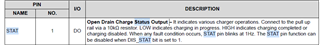
8. Verify PG LED (D13) is on.
If we remove JP17 to disable charge, as said in 2), PG LED (D13) will be off as it is connected to STAT
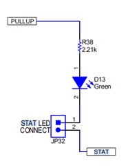
The LED will be OFF is charge is disabled.
