This thread has been locked.

If you have a related question, please click the "Ask a related question" button in the top right corner. The newly created question will be automatically linked to this question.

TPSM843B22EVM: TPSM843B22 Buck Power Module Limitations and Design Requirements for Laser Driver

Part Number: TPSM843B22EVM
Other Parts Discussed in Thread: TPSM843B22, LM25145, TPS56221, LM5145, LM5145EVM-HD-20A

Tool/software:

Hello,


We are currently running tests on a TPSM843B22EVM Step-Down Module Evaluation Module, to determine if the TPSM843B22 power module is applicable for our application.


Vin is supplied by a 15V, 600W DC power supply.

Vout is driving a diode array (to simulate a high-power laser emitter) and is set to 5V.


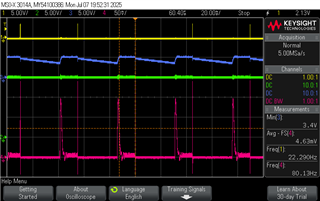
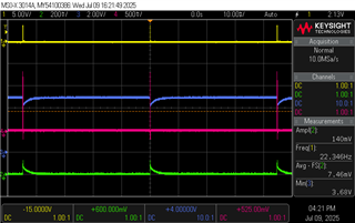
We are attempting to send high current (100-150A), 5V pulses to the load through a laser driver. We’re controlling the current, width and frequency of the pulses. From my testing, the power module seems to become unstable around 100A, 100us, 1kHz (see oscilloscope shots below).


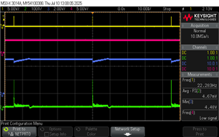
FSEL=2200Khz             MSEL=HCL:2pF:2ms

  1. Trigger signal (controls the frequency/pulse width)
  2. Current monitor at the laser driver (scale: 40A/V)
  3. Vout of the TPSM843B22 Power Module
  4. Current Probe on the input of the load (scale: 1mV/A)


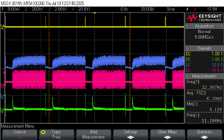
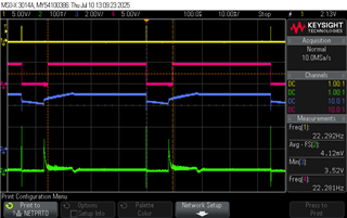
The power module appears to be going in to over current protection mode after running at these settings for a couple minutes. Is the behavior seen below expected in over current mode? Vout is pulled down to ~1V and becomes unstable, the frequency must be decreased to about 400Hz before operation is restored.


Here is a simplified schematic of the laser driver’s current source for reference. Most of the current to the laser comes from the capacitor bank, the power module supplies supplemental current during the pulse and charges the capacitors between pulses.

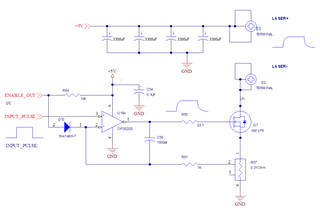
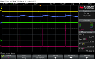
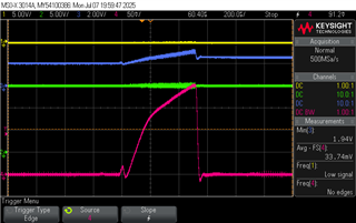
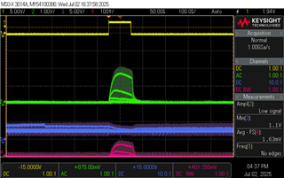
During the operating conditions described above, the current through the Power module spikes to 20A every time a pulse occurs.


I attempted to increase the output current to 120A and damaged the power module (It only allows small amounts of current to pass, otherwise Vout gets pulled down to 2V).


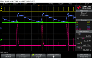
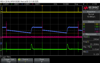
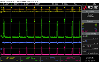
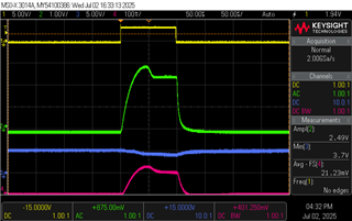
In the scope shot below, input power (red) comes from the 5V rail of an ATX power supply (No Power Module), otherwise the operating parameters are the same. This is to demonstrate the current waveform through the power module.


  1. Trigger signal (controls the frequency/pulse width)
  2. Current monitor at the laser driver (scale: 40A/V)
  3. Voltage across the capacitors
  4. Current Probe on the input Power


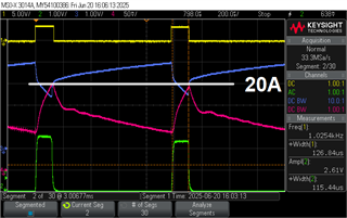
Should we expect the power module to be stable if the current peak is below 20A at 15Vin/5Vout?

Vout of the power module drops from 5V to 3.7V. Is this voltage drop too large?

When powered, we have a capacitor bank of 13.2mF (four 3300uF capacitors in parallel) attached to Vout. Is this suitable for the power module’s operation?

I noticed no change in behavior when changing the FSEL and MSEL jumpers.


Can you please help us to understand if this power module is applicable for our use case? Are there any design considerations we can change to improve performance? Is there another DC-DC power converter that may be better suited for this application?


Thank you!

  • After reviewing your description, I can see that your application is quite different
    from the typical use case for the TPSM843B22.
    The most frequent applications are steady-state operation or transients loads
    less than or near the output current rating.

    To properly diagnose the issues you're experiencing, it would be helpful to have
    more detailed waveforms of the TPSM843B22's operation, particularly:


    VIN and VOUT voltage waveforms during pulse and steady events
    SW node voltage with shorter time division without the persist on.


    There are a number of protections on the device ocp, overtemperature, undervoltage protection.
    There is a high and low side current limit.
    16 cycles of high side oc results in a hiccup.
    LS oc results in hs side fet skipping a pulse.
    The OT (165C with 12C hystersis) and UVP (delay of 7xss cycles) results in a hiccup and restart.

    Power dissipation could be high on a 15V to 5V at 2.2MHz with high average output current.

    Also, the 4x3300uF could be influencing the control loop. The esr of the 3300uF form a zero in
    the loop which could push loop bandwidth out where the phase margin is low.
    The falling edge sw node jitter can be observed in steady state
    and with less extreme load step to assess stability.
    .

  • Hi David,

    The previous explanation Ian sent was with FSEL 500KHz.  We tested all FSEL options. originally, they all somewhat worked. In the end we could not get the module to work with any, not even 500KHz.

    We did some more testing today; and were able to get the module to output 5V if we selected the MSEL to be between pins 7 and 8.

    We were not able to get 7V.

    Here is a shot of the input (CH2) and output (Ch3). we are triggering our laser driver at 22 Hz.

    Ch4 is the Module's 5V supply current into our driver.  the current probe is 10mV/A

    This is the same, if the trigger frequency is 150Hz:

    The following two images are if we select a 7V output from the module. As you can see, it does not ever reach 7V. this is without any trigger pulses to our driver.


  • The TPSM843B22 has an integrated 330nH inductor and high side current limit (~26A),

     low side sourcing (~21A) and sinking current limit (7A).

    With 15V to 5V at 500kHz, the inductor ripple current is > ~24A.     With the load current greater than 14A, the high side current limit will be exceeded.   At 0A on output with 5V output, the sinking current limit threshold may be exceeded.  

    The device has 1, 2 and 4ms fixed soft starts.  The inrush current will be significant if the

    output capacitance is 4x3300uF and soft start time is short and inrush current will be greater with 7V output vs 5V.     

    1500kHz and 2200kHz switching frequency should work though the power dissipation will be higher. 

    Decouple the laser module and use a passive or eload on the TPS and check the performance of power up and steady state. 


  • Hi David,

    Thanks!

    We have an interesting update. we tested another laser driver unit and the TPS module works now. We will continue our evaluation.

    We don't understand why the original driver still works with the ATX supply, but we won't spend time on that.

    You mention a high ripple current when stepping down from 15V to 5V. Can we observe the inductor ripple current?

    How much will the ripple current be if we use 12V instead of 15V, and a 7V output instead of 5V?

    The TPS module does not have a heat sink. Do we need to provide a heat sink to allow a 12A to 15A load current? 

    Before we spend much time on the evaluation, it seems to me that you don't believe it is a suitable solution to our application?

  • The good thing and not so good thing for a power module is the inductor is integrated into the package. 

    The TPSM843B22 power stage is more optimized for lower output voltages like 0.8V to 1.2V. 

    With the inductor constraint and your unique use case, it is difficult for me to gauge if TPSM843B22 is suitable or not.   

    The TPSM843B22 also has discrete settings for soft start, current limit and integrated loop compensation which reduces external components but makes it less flexible.    I am not recommending the TPS56221, but a device with similar features could be better.  The device has external soft start, adj. current limit, external loop compensation and could give you the flexibility. The input voltage max is 14V which does not give you much headroom and is lower than the 15V.     The LM25145 is interesting but is a controller with external fets

    If using a converter (controller+fets integrated) there is flexibility on choosing the inductor but not the power stage.  If using a controller with external fets, there is flexibility of optimizing the fet ratio and inductor.   For example 12V to 1V, the low side fet is on longer and to reduce conduction losses will have lower rdson than high side fet.  

    The TPSM843B22 integrated loop compensation is more suitable for application optimizing for less Cout. 

    The integrated Lo and external Co form a double poles in the control loop and the integrated compensation was designed assuming a range of cout.       More Cout does not always translate to good transient response, more Cout can lower the loop bandwidth and result in slower response time.   i think an externally compensated converter or controller will give you the knobs needed to work around the Cout needed to support the high current pulses. 

    Measuring the inductor current on the TPSM843B22 evm is not possible, since vout pins are soldered to board. 

    The excel calculator can be used to estimate the ripple current  it is in (cell F56)

    https://www.ti.com/tool/download/TPSM843B22-A26-A22-CALC

    For power dissipation, webench can estimate the device junction temperature. 

    If I reading the oscope plot correctly, the ATX supply voltage drooping to ~2.5V.  Drooping this much on TPSM843B22 will trigger uvp. 

  • Hi David,

    I looked at the LM25145. the webpage offers an evaluation board (LM5145EVM-HD-20A), but it is for the LM5145.  Are they comparable devices?

    Regarding our tests with the TPSM843B22, we took some comparison shots between it and the ATX supply.

    the supply voltage and current waveforms look very different. we would like to understand why.

    ATX supply:                                                                                                 TPSM843B22


  • The LM25145 and LM5145 are comparable devices, but with different voltage ratings. 

    The ATX supply does not have protections.   

    Without SW node waveform for confirmation, I suspect the TPSM843B22 has UVP triggered. Load step drops the output voltage

    below the uvp and the device shuts off for 7xsoft start times before attempting restart. 

  • thanks. I'll get plots with the SW and PG nodes.

    7xsoft start times = 28mS in our case. that would explain the long ramp.

    I read that the undervoltage kicks in if the output drops below 80% of VREF. I also read that Vref is 0.5V. is that true? because in my plot, the output does not drop to 0.5V before the 30mS descending ramp occurs.

  • David,

    here are the plots with SW and PGOOD.


    if I reduce the laser current, I can get the voltage to be steady:

    I noticed that if the supply current does not peak to 20A, the converter can sustain the voltage

  • This is uvp

    Yes, uvp triggers at 80% of VREF on the FB pin.   

    FB pin voltage of 0.5V is 5V output voltage  

    and PG goes high when output is ~90% of 5V.   

  • I'm looking to order the LM5145EVM-HD-20A, hoping it will serve our purpose.

    Is there a way to use webench or another tool to help assist in the selection?

    I downloaded the "LM5145 Quickstart Design Tool", but not really sure how to use it.

    I should open another thread to talk about this different controller in particular, correct?

    Regards,

    Victor

  • yes,   use Power Designer   webench.ti.com/power-designer and enter the input voltage, output etc.   

    Click view designs     and several choices are presented. 

    or type the part number in the search box on ti.com and go to the bottom of product folder. 

    Some devices are supported by different groups or persons in a group etc. so starting a new thread is quickest way to get to right group.