


Tool/software:
Testing a board assembly with this regulator, I needed to be able to turn the 24VDC input power on briefly while probing, to avoid having to align a scope probe on very tiny contacts with live power. Align probe, watch scope, press foot switch to connect the 24VDC supply. Everything's working great for a few minutes....and then on one power-up, there's smoke everywhere. Time interval between cycles was on the order of 30 seconds; long enough to locate the next node to test, get the scope probe tip lined up right, verify no shorts, then look at the scope screen. I was checking low voltage 3.3V connections on the processor, where no 24V is present.
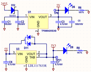
The TPSM84205EAB regulator module failed short-to-Vin, dumped 24V onto the 3.3V linear (5.5Vmax in) which failed short-to-Vin, and thereby dumped 24V onto both the 5V and 3.3V rails. And every IC on the board went up in smoke. :-(
Is this a behavior that might reasonably be expected? I don't see anything in the datasheet that would suggest so. There's much talk of soft-start, over-current, over-temp and other protections, but nothing warning of random failures on startup that would blow up an entire board.
I'm adding TVS diodes all over the place to try to intercept a fault and pop a polyfuse before every IC on the board dies. I'm also looking at other regulator alternatives, which I'll be power cycling to verify they don't have a similar failure mode. And I'll be testing some other examples of this same part to see if I can replicate the problem in a less-lethal environment. Is repeated power cycling something that could induce a failure?
