Other Parts Discussed in Thread: TLV61047
Tool/software:
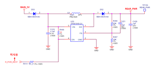
We are using the TPS61040-Q1 to supply power to a rear-view camera as follows:
-
Vin = MAIN_5V = 4.05V
-
Vout = REAR_PWR = 9V
-
Load current (when REAR_PWR is operating normally): 170mA
-
Inductor: L9 = 10uH, part number: PNL4020-100M
The circuit receives 5V from MAIN_5V and boosts it to supply 9V to the REAR_PWR line, which is used exclusively as the input power for a camera.
[Issue Description]
Under the above conditions, when no load is connected to the REAR_PWR line, the output correctly shows 9V.
However, when the REAR_PWR line is connected to the camera, the system fails to operate.
(Notably, the REAR_PWR line is supplying power to the camera only — no additional load.)
If the Vin voltage is 4.3V or lower, the issue occurs as described.
When Vin is increased to 4.4V or higher, and the camera is connected, the system operates normally.
Even at Vin = 4.3V or below, the output remains at 9V if the camera is not connected.
[Questions]
-
The datasheet specifies the input voltage range of TPS61040-Q1 as 1.8V to 6V. Why does the device only operate properly with a load when Vin is 4.4V or higher?
-
We would like to ensure stable operation at Vin = 4.0V, as per the original design. What changes would you recommend to achieve this?
Thank you for your support.
Remark : Please find attached the datasheet of the inductor(PNL4020-100) currently used in our design, along with the schematic for your reference