This thread has been locked.

If you have a related question, please click the "Ask a related question" button in the top right corner. The newly created question will be automatically linked to this question.

TPSM365R6: layout info (TPSM365R6) is urgently needed

Part Number: TPSM365R6

Tool/software:

Hello, 

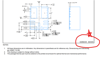
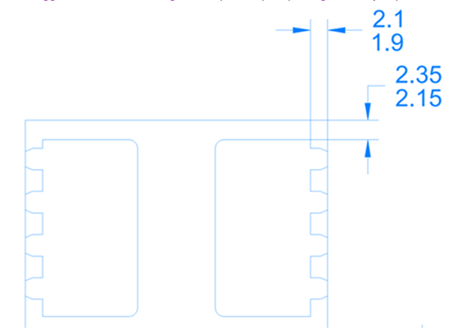
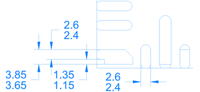
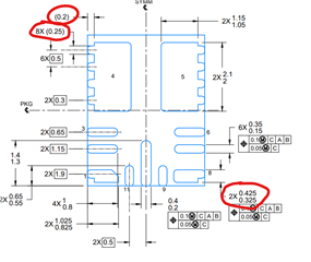
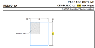
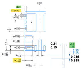
for footprint creation we have this question: we are pretty sure that the decimal point must be shifted (see attached images). Could you help us to confirm this information to be in sync, please?

The info is urgently needed; in case you're not the right person to reply, please forward the topic to the responsible person.


Thank you!

  • Hello Marius 

    Please download the latest datasheet at https://www.ti.com/lit/ds/symlink/tpsm365r6.pdf and double check the mechanical drawing. I cannot find the the number s '2.1 1.9' or ' 2.35 2.15' 

    -EL

  • Thank you, Eric Lee!

    I forwarded the info to my colleagues. I'll keep you informed about the status. 

    Best Regards, Marius

  • Thanks for choosing TI. Please feel free to contact us if you have any question.
    -EL

  • Dear Eric Lee,

    The spec from the provided link show the right decimal point, but there is some info missing; here's what the colleagues from layout wrote:
    "1.- The distance from the biggest terminal to the edge of the plastic quad package, could you provide the nominal dimension for this?

    2.- We are not pretty sure which the width of the terminal is for the pins 1,8,9,11. It may be similar to the pin 7, but we want to make sure of it to place the correct pad and avoid having a shortcut with the tracks that these terminals will have."

    From your TI's colleagues in Europe we go this answer, but the info is not found in the newest spec from the link you provided two day ago:

    1. "We were a little unclear on which orientation you were inquiring about, so we have provided both of the possible terminal to package edge measurements. The nominal distance to the top of the package would be 2mm and to the side would be 2.25mm."
    2. "If we do not include the extra pad width due to the non-uniform shape, the width of pins 1, 8, 9, 11 are all a nominal 2.5mm. If you include the larger parts of pin 1 and 8, they are a full nominal width of 3.75mm."


      Could you include this into the spec? Then, my colleagues from layout team would have the complete information to create the pads correctly.
      Thank you!
    1. Hello Marius 

      I think they are all mentioned in the mechanical drawing. 

      Please let me know who do you work with for this matter  (TI person in Europe/TI's colleagues in Europe

      -EL 

    2. Thanks for sharing the contact info. In order to avoid a confusion, I wish to use email to discuss this issue together. 

      -EL

    3. Hello Marius
      Please keep communicating with the team in Europe. They returned back and started working in the office. I will close this thread.

      -EL