This thread has been locked.

If you have a related question, please click the "Ask a related question" button in the top right corner. The newly created question will be automatically linked to this question.

BQ25611D: BQ25611D Not Entering Constant Current Mode During Charging (Li-ion 5200mAh Pack)

Part Number: BQ25611D

Tool/software:

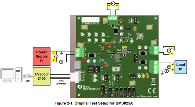
We have been testing the BQ25611D charger IC configured for our Li-ion battery pack (5200mAh, 3.7V nominal, 4.2V max), and we have encountered an issue: the charger is not entering or operating correctly in the Constant Current (CC) mode during the charging cycle.

Battery Key Specs Recap:

  • Capacity: 5200mAh (typical)
  • Nominal Voltage: 3.7V
  • Max Charge Voltage: 4.2V ± 0.03V
  • Fast Charge Current (0.5C): ~2.6A
  • Max Continuous Charge Current: ≤3A (within BQ25611D limits)

Expected Charging Behavior:

  • Pre-charge at ~100–180mA (for battery voltage < 3.0V)
  • CC mode with up to 2.6A constant current (battery voltage between ~3.0V and ~4.1V)
  • CV mode at 4.2V with tapering current until termination (~60mA)

Issue Details:

  • The charger fails to enter or sustain CC mode as per the configured fast charge current (2.6A).
  • Observed charge current remains below expected CC current levels during the charging phase where VBAT is between 3.0V and 4.1V, with the charger current gradually decreasing instead of maintaining a constant current.
  • Charging does not follow the expected CC + CV pattern, impacting the overall charge time and efficiency.

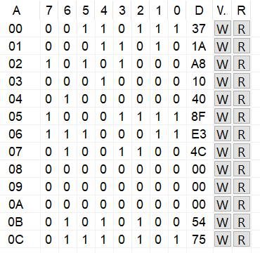
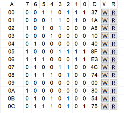
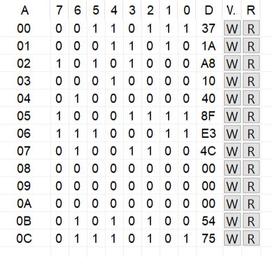
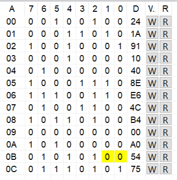
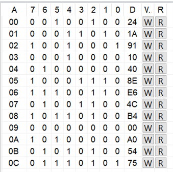
Configuration Summary:

  • Fast charge current set to 2.6A (REG02 = 0x29)
  • Charge voltage set to 4.192V (REG04 = 0xB0)
  • Pre-charge current set to ~128mA (REG03 = 0x10)
  • Termination current ~60mA (REG03 bits)
  • Input current limit set accordingly to 3A (via REG00/REG01)

We kindly request your support to investigate the root cause of the failure to operate in CC mode and advise if the current register settings and hardware setup align with the BQ25611D datasheet and recommended operating conditions.

Please let us know if additional data logs or measurements are needed from our end to assist troubleshooting.

  • Hello,

    There are multiple things that could be going on here.

    1. First, with a battery voltage of 3.0V, you are most likely in MINSYS. In MINSYS the BATFET acts as an LDO and will heat up at high current, preventing full charge current from being realized.

    2. Second, input current limit (IINDPM) or input voltage limit (VINDPM) may be activated due to external load on the system. At this point, the battery current will be lowered to prioritize the system load.

    Please provide the full register readout of the device in the reported states.

    Regards,

    Mike Emanuel

  • Hello,
           Please refer the attached file 
    3364.BQ25611D.csv

  • Hello,

    What is the BAT, SYS, VBUS pin measurement when this is happening? What is the measured charge current, SYS current, IBUS current?

    Regards,

    Mike Emanuel

  • Below are the measured details

                   VBUS = 4.7v //Charger In volt
                   VSYS = 4.23v //Charger Out volt
                   BAT = 3.1v //normal 3.1v, charger connected 3.5V


                   ISYS = 1.7A //Charger Out Current
                   IBUS = 1.7A //Charger In Current


                   Charger Rating 5v-2A. 

  • Hello,

    Something is not consistent here. It is claimed the part is not in MINSYS, however the SYS voltage is at least 700 mV higher than the battery indicating the BATFET is in LDO mode. If the BATFET is in LDO mode, it will be hard to pass full charge current to the battery. Please report the charge current in the above setup. The same current in and out of the buck converter does not make sense.

    Please share a schematic as well.

    Regards,

    Mike Emanuel

  •  Hello  

    REG configs

    We're using BQ25611D-EVM only. Battery which has 3.7V before connecting to the setup.  


    VBAT = 3.7V (no charging), 4.12v (Charging) 

    VSYS = 4.2V 

    VBUS = 5.08V  

    No-Load Condition 

    IBAT = 1.09A 

    ISYS = 0 

    IBUS = 1.03A  

    Load Condition 

    IBAT =  1.09A 

    ISYS =  1.22A 

    IBUS = 200mA

  • Hi,

    We are working on it and will get back to you soon.

    Thanks,

    Ning

  • Hello,

    Please share a schematic as requested. Please report I2C registers when the issue is happening. Previously provided registers do not paint the whole picture as the adapter is removed.

    Regards,

    Mike Emanuel

  • Hello  , 
                          We are not using custom board, we are using EVM only.

  • Hello,

    Please report the I2C registers in total when the issue is happening. Previously provided registers do not paint the whole picture as the adapter is removed.

    Regards,

    Mike Emanuel

  • Hello  
                        Please refer below images
                              
                        Charger Disconnected:
                       

                       Charger Connected:
                       

  • Hello,

    We are missing something here. Can you follow the EVM test procedure and see if that works as expected as a starting point?

    Below are the measured details

                   VBUS = 4.7v //Charger In volt
                   VSYS = 4.23v //Charger Out volt
                   BAT = 3.1v //normal 3.1v, charger connected 3.5V


                   ISYS = 1.7A //Charger Out Current
                   IBUS = 1.7A //Charger In Current


                   Charger Rating 5v-2A

    These measurements seem to point to an issue as MINSYS is 3.5V. A 3.5V battery should not have a 4.23V SYS rail.

    Regards,

    Mike Emanuel

  • Hello  
                   We had followed EVM test procedure as per below 
                     

    And this is the setup


    Test Results of Initial Settings

    1. Battery Disconnected, Only Electronics Load Connected

    • VBUS = 5.07 V

    • IBUS = 470 mA

    • VSYS = 4.145 V

    • ISYS = 520 mA (CC)

    1. Battery Connected, Electronics Load Disconnected


    Note: Without charging, VBAT = 3.4 V

    • VBAT = 3.5 V

    • IBAT = 445 mA

    • VSYS = 3.8 V

    • ISYS = 445 mA

    • VBUS = 5.07 V

    • IBUS = 400 mA

    REG Dump


    Charger Mode Verification

    Enable Load  and take measurements as follows

    Note: Without charging VBAT=3.4v,

    • VBAT= 3.5V

    • IBAT= 445mA

    • VSYS=3.8V

    • ISYS= 445mA

    • VBUS=5.07V

    • IBUS=400mA


    Change Load  to 3.7V and take measurements as follows:

    No battery, but electronics load connected as mentioned in the test setup

    • VSYS = 3.7 V (CV)

    • ISYS = 500 mA

    • IBUS = 470 mA

    • VBUS = 5.11 V

    When the battery is connected at this point:

    • The electronics load draws 300 mA

    • The battery input (charging current) is 230 mA

    • No gauge is connected; the battery is connected directly


    Can we know what is a reasonable value for the MINIMUM SYSTEM VOLTAGE would be for our battery setup?


  • Hello,

    I need a more of an up to date summary of what the issue is here... The last post was a lot of information, what is not as expected?

    However, it is worth noting you cannot force a voltage on VSYS. This is either at MINSYS or above the battery voltage (coming from the converter) and should not be forced with electronic load or power supply.

    MINSYS depends on your application. What does your load support and what does that voltage need to be? You should make your MINSYS at least this. However too high and the BATFET is in LDO mode longer, potentially reducing charge current.

    Regards,

    Mike Emanuel