This thread has been locked.

If you have a related question, please click the "Ask a related question" button in the top right corner. The newly created question will be automatically linked to this question.

LM5181: Variable output, isolated DC converter 24V..5-15V, 100mA

Part Number: LM5181
Other Parts Discussed in Thread: LM5160

Tool/software:

Hi,

we are looking for feasible solution of variable output, DC isolated converter (24V to ~5..15V, <1..100mA). Input voltage is fixed 24V, output current will vary from few mAs to about 100mA.

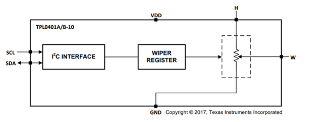
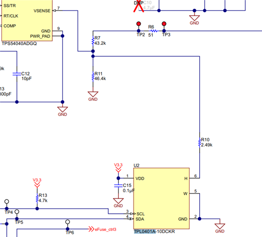
The output voltage shall be electronically adjustable in steps by e.g. external MOSFET switch or by DAC voltage connected to suitable resistor circuit of converter.

We like PSR flybacks due to simplicity and small footprint, but other approaches may be considered too.

As the project relates to sensitive measurements, low output noise/EMI is an advantage.

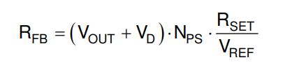
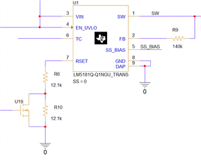
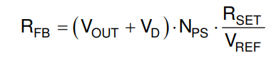
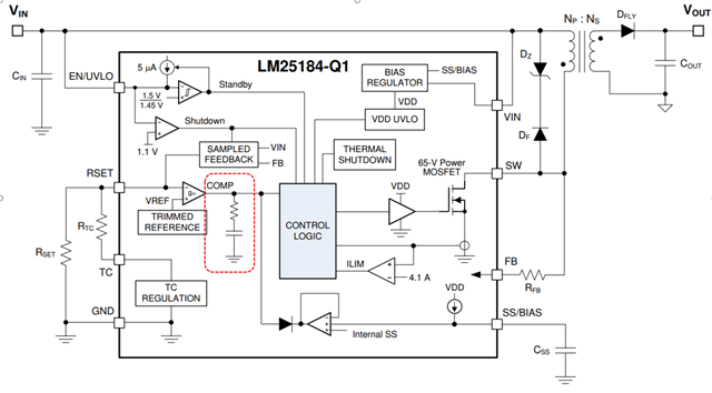
We have considered LM5181, but it is not clear what is the best way to adjust its output voltage - e.g. can we switch different values of Rset by MOSFETs ?

Btw. has LM5181 any way how to tune the control loop ?

What solution would you suggest ?

Thanks

Robert

  • Robert,

    LM5181 is a PSR Flyback with an integrated MOSFET. Rset is the resistor that is needed to generate a voltage proportional to Vout at RSET pin. From the equation below, you can see that Vout setpoint is defined by Rfb and Rset resistors. So, if you change Rset or Rfb values, Vout setpoint will change as well. 


    I have never seen the case where Vout is wanted to be changed (is always fixed), but yes, it is possible to change changing Rset or Rfb.

    Thank you

  • Hi Manuel,

    thanks for response although I am still not sure if it is feasible to use LM5181 for the intended task (variable output converter).

    "I have never seen the case where Vout is wanted to be changed"  .. does it mean TI doesn't suggest such a use case ?

    We have tried a basic simulation recently, but it was somewhat unsuccessful. The following circuit snippet demonstrates the attempt to double/halve the voltage by simple MOSFET switch.

    This circuit has resulted in undesired behavior even in case the MOSFET was turned off. The output voltage was a way up shifted compared to the same circuit without MOSFET. Also the loop behavior has changed.

    It seems either the capacitance of MOSFET has some influence or the conduction of body diode is a problem or both - simulation shows the Rset voltage reaches negative values (w/o MOSFET).

    The problem is the internal PSR function & Rset comparator is somewhat obfuscated with stuff like sampling and level shifting so we can't easily see how to design the variable output circuit.

    That leads me to following questions:

    1. Would you please consult what is a proper way how to change the output voltage by electric means ? We  need to implement two variants: a step change (e.g. by few MOSFETs and digital control) and smooth change by using of DAC.

    2. What the range of Rset is allowed and what are possible consequences when deviating from suggested 12.1k ?

    3. Is there any way how to tune control loop response - kind of external compensation circuit ? 

    4. Would you pls. elaborate the influence of external capacitance to Rset node ? We has noticed that external capacitor connected to Rset - even in ranges of tenths of pF - can change the simulated behavior a lot. I haven't found any warning in DS about it. I am afraid some parasitic capacitance may be introduced even in PCB design or in production. 

    Thanks 

    Robert

  • Robert,

    Please, see my feedback below.

    1. Would you please consult what is a proper way how to change the output voltage by electric means ? We  need to implement two variants: a step change (e.g. by few MOSFETs and digital control) and smooth change by using of DAC.

    -Rset is a control pin. It is the negative input of the internal E/A (error amplifier) that controls the input of the control logic. With this being said, it is not recommended to connect the MOSFET like that because you are adding the Coss capacitance of the MOSFET in the control loop. Similar situation with the feedback resistor between the SW node and FB pin.

    -The sampled feedback senses SW voltage and VIN at the "knee" when the secondary switching current is zero, right before the diode stops conducting, so that it avoids any I*R drop coming from parasitic components from the layout. That is why we need to avoid any extra connection than a single resistor at RSET pin.

    -We have never seen the case where Vout needs to change with this family product, so we cannot provide a solution for this. I recommend looking for an alternative solution where a variable Vout is possible.

    2. What the range of Rset is allowed and what are possible consequences when deviating from suggested 12.1k ?

    The reason of the 12.1kohm resistor is the convenience for the calculation. VREF voltage, which is the voltage connected at the positive input of the internal E/A is VREF=1.21V, so that in the equation to calculate Rfb (see below), Rfb is just the reflected Vout x10 in kohms.


    Rset can have a different value than 12.1kohm, and Rfb needs to follow the equation to be calculated. It is recommended to be in the range of kohm to reduce the power losses (especially at no load).

    3. Is there any way how to tune control loop response - kind of external compensation circuit ? 

    It is not possible because the compensator is inside the IC and cannot be modified (see below).

    4. Would you pls. elaborate the influence of external capacitance to Rset node ? We has noticed that external capacitor connected to Rset - even in ranges of tenths of pF - can change the simulated behavior a lot. I haven't found any warning in DS about it. I am afraid some parasitic capacitance may be introduced even in PCB design or in production. 

    -As mentioned above, RSET is crucial for good Vout sensing and optimal loop regulation. 

  • Ok thanks for clarification, basically this means we can't use this product for variable output as was considered.

    Would you suggest alternative isolated converter from Ti's portfolio where variable output is feasible ? We would prefer no opto or additional winding on transformer. It shall have some kind of regulation, so probably fly-buck is not ideal too.

    Thanks

  • Robert,

    The most feasible solution is a multi-winding transformer to set different Vout options. I am not aware of any isolated converter with variable output.

    Thank you

  • Hello Manuel,

    thanks for spending time with me. Anyway we have no solution yet. 

    I can't believe you have not seen design with isolated converter with variable output... That seems strange as there is plenty of materials on TI sites regarding how to control output of dc non-isolated converters (e.g. TIDU533 or SLVAEJ4).

    Isolated flybuck can be controlled by MOSFET/DAC for sure too, we have tested it e.g. with LM5160, but we would prefer some PSR type.

    Would you kindly consult this with your colleagues, hopefully someone would have an experience with variable output designs.

    Thanks

  • Robert,

    Apologies for the incomplete answer. I reviewed the TIDU533 reference design that you mentioned and I we actually can use a similar technique to change Vout using LM5181. In the reference design, they use a potentiometer TPL0401A to change one of the feedback resistor of the buck converter. In our case we can use the same potentiometer (or similar) to change RSET resistance. The advantage of a potentiometer is that it will not add any capacitance to the final RSET resistance value.

    TPL0401A has an internal I2C Interface that you can use to connect to a MCU and control the resistance at the potentiometer.

    From the equation Rfb=(Vout+Vd)*Rset/Vref, you can estimate the min and max values of RSET to get 5V<Vout<15V. After that, I recommend to implement a similar divider than the reference design (see below). In your case, you do not need R7, but just R11, R10 and the pot. When the pot is 0ohm, you will have an Rset=~R10=Rsetmin. On the other hand, when the pot is very large resistance, you will get a Rset=~R11=Rsetmax. I hope this helps.

    Thank you