This thread has been locked.

If you have a related question, please click the "Ask a related question" button in the top right corner. The newly created question will be automatically linked to this question.

TPS2663: TPS2663: TPS26631RGE short circuit

Part Number: TPS2663


Tool/software:

Hi, 

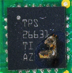
we have encountered multiple incidents, where the e-fuse IC failed, resulting in a short circuit between VIN (Pin1&2) and VOUT (Pin17&18), when the power supply was turned on. We have tested it with various settings on the lab power supply and the e-fuse was always destroyed:

Lab power supply voltage set [V] Lab power supply current limit [A]
48 2
48 1
48 0.05
36 0.2
20 0.2

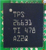
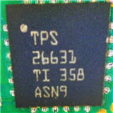
We have also noticed that this may be related to issues with the batch. The TPS26631 with the identification 'TI 478 AZ2Q' always broke. However, when the broken IC on the same PCBA was replaced with an IC bearing the identification "TI 358 ASN9", it suddenly worked with no issue.

This is our design:

  • Hello quan,

    Is there any possibility of transient voltage at VIN which could exceed the device abs max? 

    I don't see any TVS diode at input to protect against such trainsets. Please help with waveform with VIN, VOUT, IIN and FLT

    Can you check this batch on TI EVM for confirmation?

    Thanks

    Amrit 

  • Hi Amrit,

    There is no possibility for a transient voltage higher than the devices abs max VIN, because I tested it in the lab with a bench power supply. The design has also TVS-diode to protect against such transients. 

    CH1 -> VIN, CH2 -> VOUT, CH3 -> FLT

    I will provide with the IIN at a later time but it didn't look suspicious.  

    Unfortunately we have no EVM for this matter.

  • Hello Quang,

    Looks to be power supply slew rate is very slow which causing the VOUT following the VIN after fully enhanced.

    I don't see any abnormality in this waveform.

    I will check the LOT details that you have shared. Our devices go through test program before shipping. 

    Thanks 

    Amrit