This thread has been locked.

If you have a related question, please click the "Ask a related question" button in the top right corner. The newly created question will be automatically linked to this question.

BQ79600EVM: Power-up with BQ79600EVM and custom BQ79718V-Q1 based desing

Part Number: BQ79600EVM
Other Parts Discussed in Thread: BQ79718V-Q1, USB2ANY

Tool/software:

Hello,

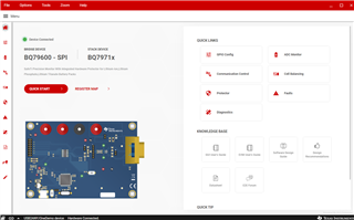
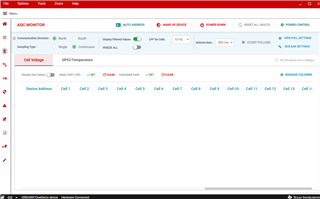
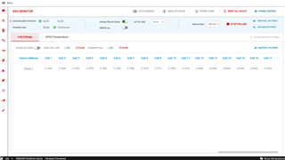
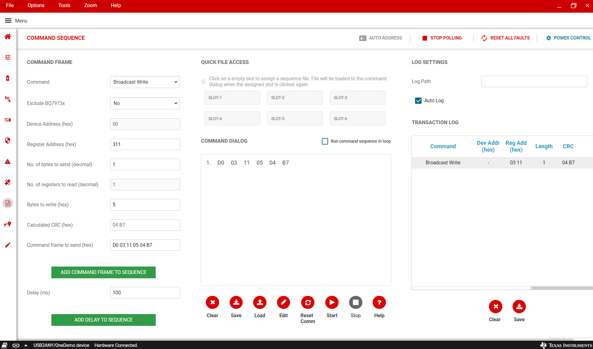
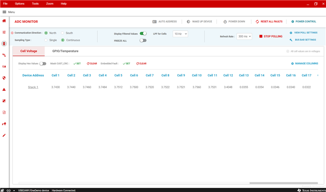
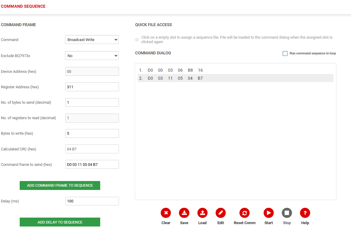
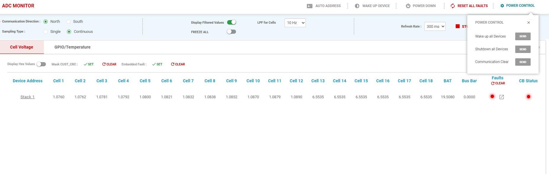
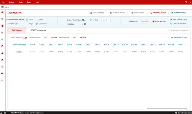
I'm trying to power-up my new PCB design that is a cell monitor based on BQ79718V-Q1. After some electrical checks, seems that all is ready to start measuring cell voltages from my battery module. I want to use the USB2ANY and the eval kit BQ79600EVM-030 to send/receive data from/to PCB cell monitor (BQ79718V-Q1). For that I use the COMH port on both sides, BQ79600 eval kit and my PCB.

Is this procedure valid to start working with my own cell monitor design?

Thanks TI Team!

js

  • Some evidences of current status

  • Hello,

    Make sure the VIF connection is COMH on the 600 to COML on the 718. Make sure your 600 is configured for USART (or SPI if this is prefered). To start polling, hit wakeup, auto address, and then the start polling button in the second screenshot you have sent.

    Hope this helps,

    Zachary

  • Hello Zachary, now it's running. Thanks!

  • Hello,

    I am using a 45.0V voltage divider instead of real battery module being cell12 my top cell. I am thinking if there is any reason why Vcell12 is 0.35V below the nominal value 3.75V  (3.75-3.4=0.35V). 

    The current through each 100R resistor is the same 37.5mA so the voltage drop for each R should be the same. R tolerance of 1% could not be the problem.

    Is there any check that I should do?

    Thanks

  • Hello, I've measured with a voltmeter the cell differential voltage and all voltages are close to 3.75V. I use the BQ79718 but in practice I only use 12 cells so [cell18:cell 13] are not used and connected following TI DS recommendation:

    With the GUI voltage for cell 12 is 3.4049V but with voltmeter VC12-VC11=3.754V. Below the GUI version used:

    Any suggestion to find this difference?

    Thanks!

  • Hi js,

    A recommendation would be to change the num of cells to match your design.

    The register to be written would be DEV_CONF2, NUM_CELL. For example on how to change, please look at the Command Dialog box below.


    Best Regards,

    John

  • Hello,

    I've configured the stack send the command sequence below:

    But I got the same result, Cell 12 keeps same voltage of 3.4V different from expected 3.75V:

    I'm using SPI bridge communication because I don't have available UART in my PCB. I read from the Help menu in Command sequence tab that to send commands I have to use UART:

    Is because SPI communication used that the voltage on Cell 12 doesn't change? Or something wrong using the GUI?

    Thanks

  • Hi JS,

    I believe hitting the polling button would reset the num_cell to the maximum of 18. You can see that the cells 13-18 are still polling data. I have attached an image where it shows the device is only polling 1-12.

    This is done by 1. hitting the poll button before the command sequence and 2. adding the below command sequence, which will restart the adc with the adjusted num_cell settings. SPI/UART communication should not affect this.


    Best Regards,

    John

  • Hello John,

    Now voltage on Cell12 is correct 3.75V

    Thanks

  • Hello, for GPIOs I need the command sequence to configure the BQ79718V correctly on my PCB design. Below the definition that I need:

    GPIO0 as RX

    GPIO1 as TX

    GPIO2 as NFAULT

    GPIO3, GPIO4, GPIO5, GPIO6 and GPIO11 as ADC input

    GPIO8, GPIO9 and GPIO10 not used

    This what I am reading now:

    Can you help me with GPIO command sequence?

    Thanks

  • Hi Js,

    The datasheet registers that allow configuration of GPIOs are in the GPIO_CONF register. One can write to the registers for the desired mode.

    For new topics, please form them on a new thread.

    Best Regards,

    John