This thread has been locked.

If you have a related question, please click the "Ask a related question" button in the top right corner. The newly created question will be automatically linked to this question.

UCC256402: Questions regarding FB, BIAS, LL/SS, VCC

Part Number: UCC256402
Other Parts Discussed in Thread: ATL431

Tool/software:

I am a  San Jose State University Student from the Spartan Racing FSAE team. I just want to ask a few question regarding the UCC256402 controller chip for a DC-DC that is suitable to step 300-400V down to 24.5V.

  1. My team is designing a very compact converter unit, which has a small transformer and wish to discard the bias windings. So we decide to use an isolated DC-DC converter to supply VCC from the secondary output. How much current should this converter supply to the UCC256402?  Also, Page 18 of the brief sheet has a table describes that ratio of 0.6 can be achieved by making the BW pin see 4.5k resistance (option 6) or short to ground (option 8). But the option 8 is not shown in the datasheet. In our case, would you recommend shorting the BW to ground?
  2. How does the BMT threshold affect the system stability?( Currently BMT_H is 0.6V) In short words, how do I determine the threshold I need knowing that my BMTL/BMTH ratio is currently set at 0.6? 
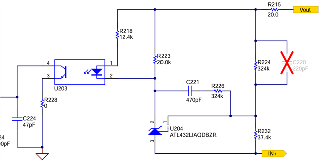
  3. The the feedback chain I am using the ATL431 in comparator mode. I am still not sure how the FBreplica voltage is being used for control effect as the change of voltage happen rapidly when the output voltage is close to 24.5V. So is this Feedback chain only used to trigger burst mode in my case? I also need to read more about compensator for the feedback circuit.
  4. In the beginning of the datasheet, the UCC256402 variant is described as having no soft-on/soft-off function. For the capacitor, can I choose any value between 4.7 to 470nF? How is the resistor divider configured to limit max switching frequency to 350kHz?

Much Appreciate you help,

Wenjin Wu

  • Hi,

    1. 10mA is enough to supply in Vcc. I will recommend using option 6 for disabling BW. 

    2. Setting BMTH will not affect the stability. After setting BMTH, you need to tune your feedback. BMTH and BMTL thresholds are used to determine at which power you want to enter in burst mode. That will affect efficiency of the converter at no load.

    3. I could not understand your question. Can you please elaborate it little more?

    4. This soft on/off is about burst soft on/off mode, not IC soft turn on.. I guess you are talking about Cap in LL/SS pin, the value of capacitance depends upon the time you want to give to your converter to turn on softly, the calculation is given in the end of datasheet. Resistor devider in LL/SS pin also sets BMTH threshold which limits maximum frequency of the converter.

    Regards,

    Sougata

  • Hi Sougata,
    Thank you so much for your clarifications and advices!

    1. I ask about the current needed because datasheet say RVCC can supply maximum 100mA and the UCC25640x consume max 2.7mA when running but excluding the gate current. I thought a good amount of headroom on maximum current that the DC-DC can supply or making a big capacitor bank for VCC would be great.

    2. Thanks for the information. My system will always maintain at least 60% load during normal operation. I will tune the feedback on testbench accordingly then.

    3. Sorry about the confusion. My current understanding is that the FBreplica is followed the by Vcomp during normal operation for control effect( after soft start has been completed), which determines the Vth_L and Vth_H for the VCR pin. While the generated threshold will affect the switching frequency, the feedback circuit I have operates the shunt regulator in comparator mode. So the optocoupler photon diode basically goes from off state to very bright state when the voltage of the shunt regulator change from (Vout - Vopto_diode) to 2.5V, which mean the amount of current sink from the FB pin can change from 0 to a very big amount. This would directly trigger burst mode in this state. I wanted to check if my through process was correct to reinforce my understanding of the chip and the circuits. I used the same circuit from PMP21160 reference design but without the 20ohm R215. The IN+ is same as the output ground.


    4. Thanks for the clarification.

    Best Regard,

    Wenjin

  • Hi, 

    please check R215, R218, R223 is used for providing required bias current to U204, other components are used for compensation. Please finetune your components accordingly. 

    Regards,

    Sougata