This thread has been locked.

If you have a related question, please click the "Ask a related question" button in the top right corner. The newly created question will be automatically linked to this question.

LM5190: Unexplained component failures

Part Number: LM5190

Tool/software:

Hello,

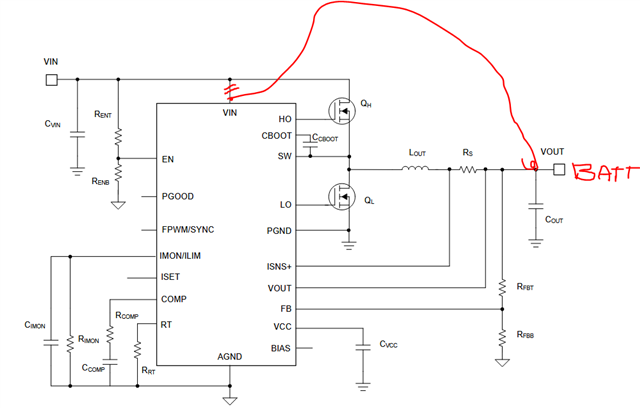
We used the LM5190 to create a circuit that limits the maximum charging current of a lithium battery in systems derived from lead-acid storage systems.

The BMS activates the circuit to limit the battery charging current to a maximum of 10A.

The maximum input voltage is 60Vdc and in any case cannot exceed 80Vdc.

The circuit always has on the output the battery voltage.

We have had unexplained component failures.

A failure condition appears to occur when the input voltage is applied when the EN pin is already enabled.

We tried connecting the VIN pin to both the input voltage and the battery (output), and in the latter case, failures seem to be more frequent.

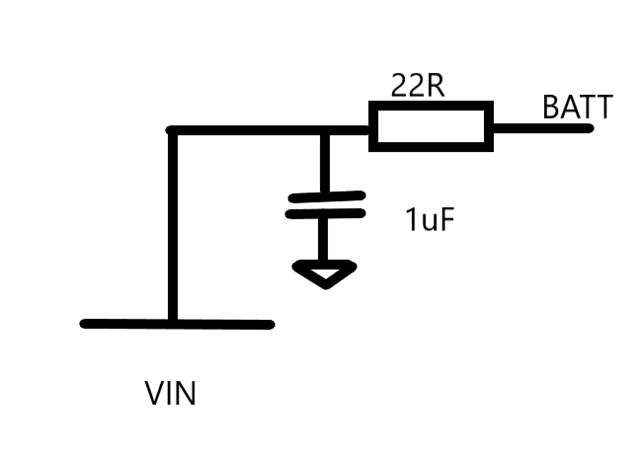
We had placed a filter on the VIN pin consisting of 22R and 1uF, but this increased the failure rate compared to connecting the pin directly to the power supply.

Does anyone know what could be causing the component to fail?

Thanks for your help.

  • Hello Marco 

    Would you please let me know if any other component failed together with the LM5190 device ? 

    We tried connecting the VIN pin to both the input voltage and the battery (output), and in the latter case, failures seem to be more frequent. ==> Would you please explain this in detail using a schematic ? Battery was charged when you connect the VIN pin to both the input voltage and the battery ? 

    -EL  

  • Hello Eric,

    VIN isn't connected to both input and battery.

    We tried two configurations.

    In the second configuration the IC is supplied from Vout that is connected to the battery.

    The battery is always present.

    This configuration was preferable to avoid damage of the IC due to overvotages on the Input, but it seems that for some reason it causes failures of IC.

    Thanks,

    Marco

  • Hello Marco 

    Would you please let me know if any other component failed together with the LM5190 device ? 

    Did you check which pin is damaged ? 

    When the VIN pin trace is disconnected, did you populate the VIN capacitor which is typically 220nF ? 

    -EL 

  • Hello Eric,

    we put a 22R resistor in series and a 1uf capacitor to filter supply voltage.

    Sometimes pin VIN results in short circuit to GND and sometimas we measure a low impedance (say 50R) between VIN and VOUT.

    Thanks,

    Marco

  • Hello Marco 

    Looks like there was an over-voltage event when you connect battery. The Abs Max rating of the device is fully tested by ATE. 

    Please add ~ 62V rated Zener diode between VIN and GND as an experiment, and try to duplicate the issue. If the Zener diode is damaged, means the amount of VIN overshoot is more than than your expectation.

    -EL 

  • Hello Eric,

    failure of IC doesn't happen when we connect the battery.

    The battery is already connected but the but the battery charger voltage is not present.

    The IC is enabled by EN pin.

    We apply 60Vdc battery charger.

    We verified that there is no overvoltage but the IC often breaks in this condition.

    If we apply the battery charger voltage with the IC disabled and then we enable it, it seems IC doesn't break.

    We noted a strange thing: with battery connected on VOUT and VIN pin no t connected to anithing, we measure battery voltage on VIN: do you know what could be the reason?

    Thanks,

    Marco

  • Hello Marco 

    I will be back after checking the IC schematic.

    -EL 

  • Hello Marco

    It is not mentioned in the datasheet Abs Max table, but actually the Abs Max of ISNS-to-VIN and VOUT-to-VIN are ~ 5.5V.

    The device might be damaged if V(ISNS-VIN) or V(VOUT-VIN) is greater than ~ 5.5V.  The body diode of the high-side MOSFET prevents this situation if the drain of the high-side MOSFET is connected to the VIN pin.  

    There is an internal MOSFET between ISIN/VOUT and VIN which can be damaged when V(ISNS-VIN) or V(VOUT-VIN) is greater than 5.5V. If this MOSFET is damaged, then V(VIN) follows V(VOUT). 

    Even if this MOSFET is not damaged, there is a possibility to turn on this MOSFET accidently if VOUT is externally supplied, but the device is not enabled. 

    -EL 

  • Hello Eric,

    thanks for the answer but there is stil something i can't understand.

    We replaced the 22R with 0R to avoid voltage drops under transients: the failure still occurs although less frequently.

    With VIN connected to VOUT (Battery), V(ISNS-VOUT) and V(VOUT-VIN) should be always about zero in all conditions, so the the failure should not occur.

    Another thing we can't understand is that if we supply the IC from the BIAS pin, the IC doesn't start without voltage on VCC pin.

    Thanks,

    Marco

  • Hello Marco 

    if we supply the IC from the BIAS pin, the IC doesn't start without voltage on VCC pin ==> This is true. The device can be enabled when VIN is high enough, EN>EN threshold and VCC>VCC_UVLO_THRESHOLD

    Since the issue happens less frequently by adding 22R, I hope you can check if any overshoot happens between VIN and GND. 

    -EL 

  • Hello Eric,

    I wrote VCC pin but I meant VIN pin, but I think your answer is correct.

    For the second point: the issue happens less frequently by REMOVING 22R an replacing it with a short.

    Thanks,

    Marco

  • Hello Marco 

    Found that there is an internal path from the SW pin to the VIN pin through two diodes.  This explains why the VIN pin voltage follows buck output voltage when the VIN pin is disconnected. This also explains the device damage. I cannot share more details in public. Please always connect the VIN pin at the node whose potential is the same as the drain of high-side MOSFET. 

    -EL