This thread has been locked.

If you have a related question, please click the "Ask a related question" button in the top right corner. The newly created question will be automatically linked to this question.

UCC28750: UCC287505DBVR Design Review for Dual Isolated Output

Part Number: UCC28750
Other Parts Discussed in Thread: TL431

Tool/software:

7041.Power Supply.pdf

Hello,

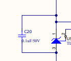
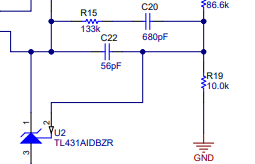
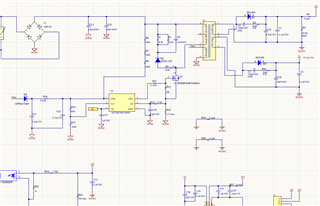
I am creating a design for universal input from 85-265VAC , 50/60Hz frequency with Two Dual Isolated output 12V,0.5A and 5V,0.2A. I have used SSR on 12V using TL431 and optocoupler feedback on UCC287505DBVR switcher Chip. I need CV output from both secondary output.

Kindly review the schematic and provide your feedback. Please let me know if you have any questions.

Thanks

  • Overall I think the schematic is fine. I would remove C20 in your schematic and add R15 and C20 shown in EVM schematic


  • Hello Tan,

    Thanks for the quick response. I just have few queries here.

    1. Can I reduce the Rstartup quantity from 3 to 1 ? What will be the wattage requirement ? currently I have selected 0.25W part and 1206 Package used.

    2. Can I also reduce 287k to 1 quanity and remove 1 ? currently I have selected 0.25W part and 1206 Package used. Can we change the package to 0603 ?

    3. To reduce the board size , I want to change the package of below parts to 0402/0201 (if feasible). Is it fine or it will impact in design anyway ?

    R11,R12,R13, C10,R16, C11, C12,C13, R15, R17, D4 , R14, R9 and other parts at optocoupler input and output .

    4. Also suggest me if I can remove few parts from the schematic to reduce the PCB size it will be helpful.

  • As long as you can find the resistor with the voltage and power spec, you can use fewer components. For example, the start up resistor need withstand the input HV. The power = Vrms *Vrms / R. If you use a 1.5M resistor, the power rating needs > 0.045W. Then you need to verity the resistor derating curve to make sure it works at your worst ambient temperature. 

    You can change the package size to shrink the board foot print, but the impact is very small. A good placement (especially caps) and transformer design can make bigger impact on your system overall size. Also, I'd recommend to add EMI filter at the input stage to pass CE/RE test.