Tool/software:
Dear Team,
we designed a simple charger for a 12.8V LiFePO battery using a TPS552872.
Below you can see the schematic and PCB layout.
We set a charging voltage of 14.8V with R41 and R42 (from the battery datasheet) and a current limit of 500mA with R1.
The input voltage (+VIN) is about 13V, so the regulator works in step-up, until it limits the current.
We set a current limitation in case we wanted to charge an almost completely discharged battery.
We put the circuit under test by connecting a constant-current electronic load instead of the battery.
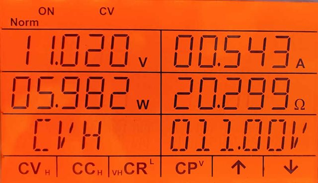
As long as the current drawn by the load is less than 500mA, the circuit works smoothly by stabilizing the voltage at 14.8V.
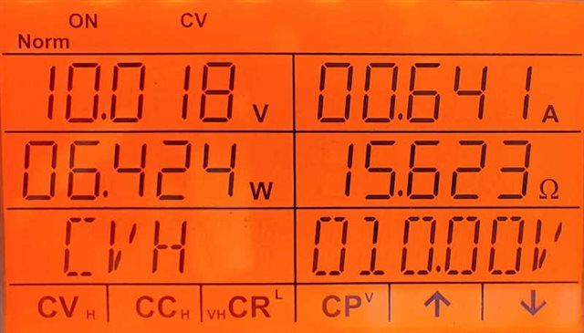
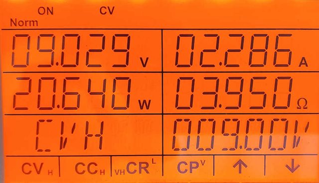
When the current exceeds about 550mA, the voltage starts to drop, but when it reaches about 9.2 volts it stops and does not drop any further, so it no longer limits the current.
Why does the voltage not drop further so as to limit the current?
Figure 1 shows the SW2 signal at 550mA; Figure 2 shows the SW2 signal at 600mA. For higher currents the signal remains the same.
I tried changing the operating frequency by changing the value of R37, but nothing changed. I also tried different values of inductance for L2.
If you need any other measurements, please let me know.
Thank you.
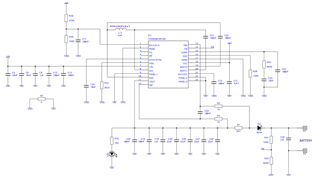
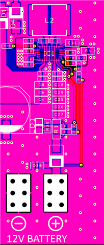
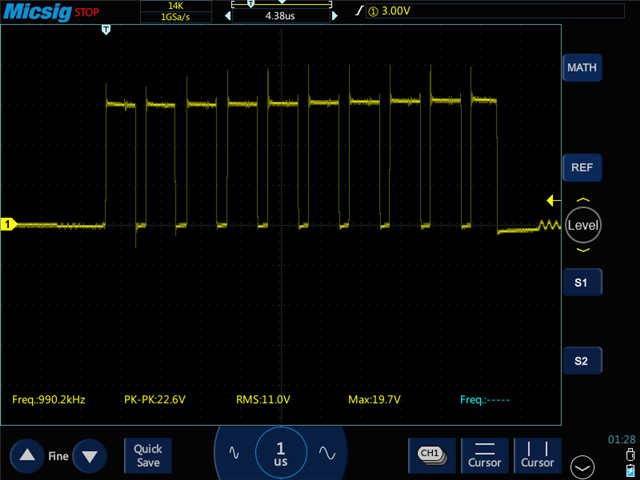
FIG.1
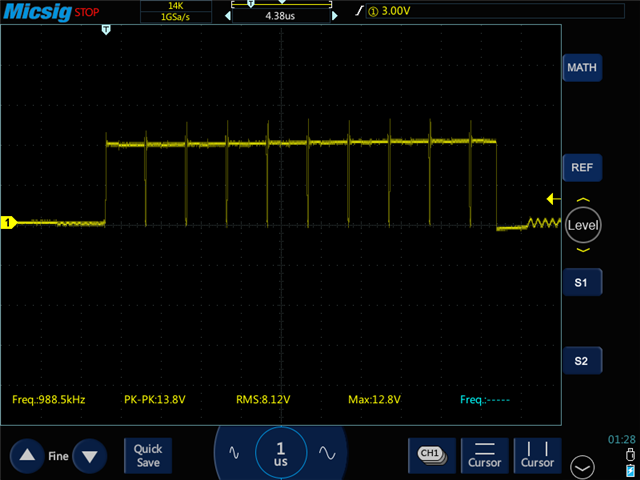
FIG.2