This thread has been locked.

If you have a related question, please click the "Ask a related question" button in the top right corner. The newly created question will be automatically linked to this question.

TPS25751: spec check

Part Number: TPS25751
Other Parts Discussed in Thread: BQ25756, , PMP41083

Tool/software:

Hi

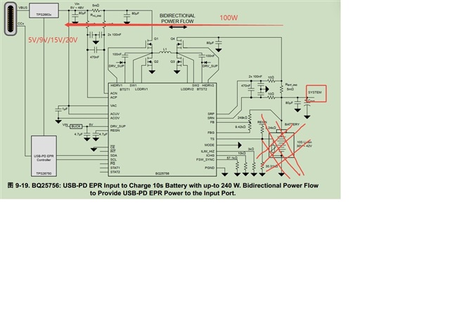
Project background: The customer's battery is powered by other chargers, and the battery can be plugged in and out. TYPE-C is not required to power the battery. The maximum external discharge power of TYPE-C is 100W. Based on my current understanding of the BQ25756 and TPS25751 specifications and the PMP41083 reference design, I have the following questions:

1. The current application is the system---->type-c in the figure below. I would like to ask, how do I adjust the input voltage of the TYPE-C device I inserted? That is, how is Vout (VBUS) switched? (My idea is that the back-end device communicates with PD through CC, and then PD uses I2C to adjust the output voltage of BQ25756. I wonder if my idea is correct? If it is correct, is there a more detailed answer?)

2. In typical applications and reference circuits, we will not use the battery in the figure. If so, can BQ25756 still work normally?

3. If the above conditions cannot make BQ25756 work properly, please recommend a buck-boost controller that can be paired with TPS25751

. Thank you

  • Hi Gareth,

    1. The current application is the system---->type-c in the figure below. I would like to ask, how do I adjust the input voltage of the TYPE-C device I inserted? That is, how is Vout (VBUS) switched? (My idea is that the back-end device communicates with PD through CC, and then PD uses I2C to adjust the output voltage of BQ25756. I wonder if my idea is correct? If it is correct, is there a more detailed answer?)

    There VBUS voltage is based off of the negotiation that happens between the USB-PD source and the TPS25751 acting as a sink. It is dependent on the supported source capabilities of the source(out of our control) and the supported sink capabilities set with the TPS25751. Typically, the max power supported by both will be negotiated. You have little control over the source PDOs in this situation, but you can modify the sink PDOs (sink contracts supported by the TPS25751).

    You can modify the TPS25751's supported sink PDOs in the Application Customization Tool by changing the supported sink pdos in the Transmit Sink Capabilities register. Here you can configure the number of PDOs, and the individual PDO voltage and operating current values.

    (My idea is that the back-end device communicates with PD through CC, and then PD uses I2C to adjust the output voltage of BQ25756. I wonder if my idea is correct? If it is correct, is there a more detailed answer?)

    You are partially correct. The TPS25751 negotiates the PD contract as a sink and will close its internal switch to provide the USB-C PD voltage to the battery charger' input. It will then program the under voltage and input current limit of the BQ25756 over I2C to ensure it does not draw more power than is negotiated at the port.

    The voltage regulation at the battery pin is almost fully managed by the BQ25756. I'm not an expert here, so I will assign this thread to the respective team and let them comment here. My understanding is that the BQ25756 will regulate the battery and charging based off of the battery voltage. The voltage is not programmable outside of setting the number of cells in your battery and certain %thresholds for different parts of the charging cycle.

    2. In typical applications and reference circuits, we will not use the battery in the figure. If so, can BQ25756 still work normally?
    3. If the above conditions cannot make BQ25756 work properly, please recommend a buck-boost controller that can be paired with TPS25751

    I will let the BQ team respond here.

    If you are using the TPS25751 for sink only with a BQ part or DC-DC converter not supported directly by the TPS25751 (as indicated in the DS and the GUI), you will need an I2C host to limit the converters power draw yourself. The TPS25751 only automatically programs over I2C for the devices specified in the GUI.

    Thanks and Regards,

    Chris

  • Hello Gareth,

    2. The BQ25756 can work without a battery, but this might be difficult to do so. The BQ25756 is designed to charge batteries. To make the BQ25756 IC provide an output voltage without a battery. I recommend the following settings:

    • EN_TERM=0
    • EN_PFM=1
    • Set the charge current to the load current
    • Increasing the output capacitance will also help here.

    Let me know if this works for your application.

    Best Regards,
    Ethan Galloway