This thread has been locked.

If you have a related question, please click the "Ask a related question" button in the top right corner. The newly created question will be automatically linked to this question.

TPS65988: Sinking and sourcing on both USB-C ports

Part Number: TPS65988
Other Parts Discussed in Thread: TPS65987D, BQ25792, BQ24292I

Tool/software:

Hi there,

I’m currently working on a design that incorporates the TPS65988, and I’d like to confirm some capabilities regarding dual-role functionality.

Is it possible for both ports on the TPS65988 to support sink and source operation? Specifically:

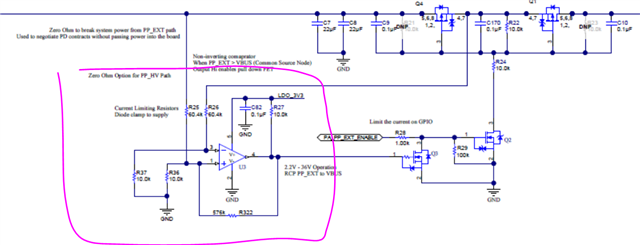
  • I’d like to support scenarios where both ports are sourcing power simultaneously (e.g., Port 1 and Port 2 both providing 5V VBUS from a shared DC/DC supply). I am using the BQ25792, and have set up proper external NFETs to make sure that the charger doesn't receive both VBUS power. Looking at the schematic, there are already two PFETs on the TPS65987D VBUS side. I guess I can do away with these BQ25792 NFETs?

  • Alternatively, if Port 1 is connected to a 5V DC/DC supply (via PP_HV1) and Port 2 is connected to a battery charger IC (e.g., BQ25792) or vice versa, I’d like Port 2 to sink power and pass it to the BQ charger when needed while the other port sources, etc. 

  • How can I configure the TPS65988 such that both ports are capable of sourcing or sinking power, is this easily done?

  • Are there any design caveats or best practices to consider, especially with regard to tying PP_HV1 and PP_HV2 and using in conjunction with BQ25792? Mainly I would like to avoid the use of 8 external FETs (4 NFETs on BQ side, 4 PFETs on TPS65988 side). 

Thanks in advance for your help!

Best regards,
Ben

  • Hi Ben,

    We will assign this thread to one of our engineers and they will respond within the week.

    Thanks and Regards,

    Chris L

  • Hello,

    I guess I can do away with these BQ25792 NFETs?

    Please refer to the device datasheet.  https://www.ti.com/lit/ds/symlink/bq25792.pdf#page=31

    How can I configure the TPS65988 such that both ports are capable of sourcing or sinking power, is this easily done?

    The TPS65988 supports dual role power.  The configuration is done with the GUI tool. https://www.ti.com/tool/TPS6598X-CONFIG

    Are there any design caveats or best practices to consider, especially with regard to tying PP_HV1 and PP_HV2 and using in conjunction with BQ25792? Mainly I would like to avoid the use of 8 external FETs (4 NFETs on BQ side, 4 PFETs on TPS65988 side). 

    I would recommend starting with the EVM.    

    https://www.ti.com/lit/ug/slvub62b/slvub62b.pdf

    Please be advised that this device is not recommended for new designs and is not compliant with the latest USBC-PD specification.

    Regards,

    Chris

  • Hi Chris, 

    Thanks for your reply. 

    Could you please be more specific rather than "refer to datasheet?"
    If I decide to use the BQ24292i charger with one VBUS input only with TPS65988 instead of BQ25792, it is possible, as long as I use the two PFETs to ensure both chargers dont supply VBUS sink to the charger? 

    What part would you suggest that can do the same as the TPS65988 series then?

    Regards

    Ben

  • Hello,

    Could you please be more specific rather than "refer to datasheet?"

    I have given you a direct link to the page/section which describes how to configure the BQ device without external mosfets.

    If I decide to use the BQ24292i charger with one VBUS input only with TPS65988 instead of BQ25792, it is possible, as long as I use the two PFETs to ensure both chargers dont supply VBUS sink to the charger?

    Can you provide a block diagram of what you are trying to do?  If you need a place to start consider the block diagrams found in the datasheet starting with Figure 9-7. TBT Notebook with PD Charging.  You can disregard the high-speed lanes and focus on the power.  Figure 9-11 will be more like the EVM referenced in the previous post.  If you want to 'OR' the power paths to the charger, then you would need an EC to manage which power path you want to sink from in the event that both ports are connected to sources.  Alternatively, you could update the unused port in real-time to only support source mode to guarantee only one power path to the charger is enabled at a time.

    https://www.ti.com/lit/ds/symlink/tps65988.pdf#page=50

    Regards,
    Chris

  • Hi Chris,

    Apologies for the lack of clarity, and thank you for your explanations.

    I can provide a block diagram if needed, but my implementation will likely follow Figure 9-7 quite closely.

    My main question is regarding the ORing of the external sink power paths. As you mentioned, to achieve this, I assume I need to implement the FETs shown on the EVM — specifically, the ones with gates connected to PPEXT1 and PPEXT2 on the TPS65988.

    I’m likely not going to have an embedded controller in my system, so I was hoping to rely on the TPS65988 reading from the SPI flash for configuration and handling the toggling of the PFET gates. 

    My understanding is that, in this setup, if one port is sourcing VBUS, the TPS65988 would automatically prevent the other port from sourcing VBUS or passing power to the charger in the instance that both sources are connected. Is that correct, and is there any risk of accidentally passing two VBUS sources to the charger with this configuration, if setup correctly with the config tool. 

    I plan on using two external FETs for the sink paths, and the source paths will be the internal paths as per Figure 9-7 block diagram. 

    Thanks again,
    Ben

  • Hi Ben,

    Could you still draw out a simple block diagram? I am a little confused on how you are using the BQ device. Is it only being used for sinking? How are you sourcing power and how will you be sinking power?

    if one port is sourcing VBUS, the TPS65988 would automatically prevent the other port from sourcing VBUS or passing power to the charger in the instance that both sources are connected.

    What do you mean when you say sourcing? Typically "source" is used to say that the port will provide power to the type-C port to an external device. I.E. sourcing 5-V from the Type-C port to a peripheral. The term "sink" is used when power is being drawn from the port into the system.

    In the block diagram in figure 9-7, both port1 and port2 are capable of sourcing 5-V and this is done somewhat independent of the other port. If one port is acting as a source, there is nothing automatically preventing the other port from also sourcing 5-V.

    In general, the two ports on the TPS65988 act independently of one another. There are some fairly limited behaviors that can depend on the other port, but typically an MCU is required for more complex behaviors and dependencies on other ports. If you are expecting ports to not support sourcing when the other port is sourcing, it may not be something easily implemented with the PD controller alone.

    Thanks and Regards,

    Chris

  • Hi Chris, 

    Correct, I will only use the BQ to sink VBUS, won't be using its internal boost at all. So my plan was to short the PPHV1/2 paths together to a 5V VBUS source, as I did with TPS65987D (only using one port). 


    I plan on implementing the exact same setup here (i.e using the internal power paths for sourcing VBUS, which will be from an external 5V DC/DC boost). The external paths will be used for sinking VBUS (i.e charging the battery/powering the load). 

    My question is, is there any risk of the two VBUS sink path switches being closed at the same time, therefore shorting the two VBUS lanes if two same chargers are connected? Or if the TPS65988 is configured correctly in the GUI, this situation cannot happen? (i.e once one path is closed, the other will not also close?). 

    I am wondering if this is all handled by the firmware or if I need some external EC as you suggested. 
    If you could confirm that would be great. 

    Kind regards
    Ben

  • Hi Ben,

    Thanks for the diagram and additional explanation. I think I understand the ask now.

    Can you see if the Multiport Sink Policy Management meets your needs here. You should still include the additional RCP circuitry when using the external paths as sink only as seen in the TPS65988EVM to ensure that RCP never happens.

    https://www.ti.com/lit/an/slvaf24/slvaf24.pdf?ts=1718908403300&ref_url=https%253A%252F%252Fwww.ti.com%252Fproduct%252FTPS65988

    Thanks and Regards,

    Chris