

Tool/software:
I need a sample code for Arduino due and STM32 code for Project purposes. Hereby i attached a schematic below. 

This thread has been locked.
If you have a related question, please click the "Ask a related question" button in the top right corner. The newly created question will be automatically linked to this question.
Tool/software:
I need a sample code for Arduino due and STM32 code for Project purposes. Hereby i attached a schematic below.
Hi Ramesh,
Attached the sample code based on msp432p401r for your reference.
But I'd like to know if there are multiple devices cascade connection requirement in your project. If not, I strongly recommend you to take a look at the new device LP5815, 3-channel I2C interface RGB LED driver, which is more cost competitive and has more advanced functions. At the same time, the GUI and EVM board are also available for your early development.
Best regards,
Felix

Yeah, thanks for the reply.
I am trying TLC5973 with Arduino Due. I am sending 48-bit data in the SDI pin; I am not able to get the correct response in OUT0, OUT1, and OUT2. Hereby, I attached my code.
"

Hi Ramesh,
Please allow me to take some time to read the code.
i will try to reply to you as soon as possible.
Best regards,
Felix
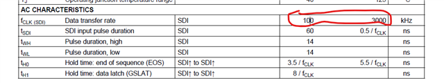
I have few updates on that. The measured cycle of two rising edges was 10.26 us in the SDI line. As per the datasheet, we need to get 0.33 to <=10 us. Am I right?
Hi Ramesh,
Based on the spec on datasheet, the supported minimum data transfer period should be larger than 10us.
Have you tried to decrease the period to have a test again?
Best regards,
Felix
Hi Felix,
I configured in code the interface with STM32L4P5ZGT6. The system clock was 80 MHz. Hereby, I attached a code and settings below. Still I am facing LED blinking issue.
Please go through it.
| Data rate | 320 kHz | 100–3000 kHz |
| Bit period | 3.125 µs | 1 / 320 kHz |
| Reset pulse | 100 µs | >80 µs min value |
| EOS hold | 20 µs | Conservative padding 2 bits (0 0) |
| GSLAT pulse | 30 µs | min value |
| Manchester | 1.56 µs half-bit | 50% duty cycle |
/* USER CODE BEGIN Header */
/**
  ******************************************************************************
  * @file           : main.c
  * @brief          : Main program body
  ******************************************************************************
  * @attention
  *
  * Copyright (c) 2025 STMicroelectronics.
  * All rights reserved.
  *
  * This software is licensed under terms that can be found in the LICENSE file
  * in the root directory of this software component.
  * If no LICENSE file comes with this software, it is provided AS-IS.
  *
  ******************************************************************************
  */
/* USER CODE END Header */
/* Includes ------------------------------------------------------------------*/
#include "main.h"
#include "math.h"
#include "stdio.h"

/* Private includes ----------------------------------------------------------*/
/* USER CODE BEGIN Includes */
#define TLC5973_DATA_PIN GPIO_PIN_0
#define TLC5973_DATA_PORT GPIOA

/* TLC5973 Commands */
#define TLC5973_WRITE_CMD 0x3AA  // Write command (10 bits) - 001110101010
#define TLC5973_GSLAT_CMD 0x000  // GSLAT command (all zeros for latch)
#define NUMBER_OF_LED 1

#define DATA_RATE_KHZ 320      // 320kHz data rate (within 100-3000 kHz range)
#define BIT_PERIOD_US (1000 / DATA_RATE_KHZ)  // ~3.125μs per bit
#define T_HIGH_MIN_NS 14       // Minimum high pulse duration
#define T_LOW_MIN_NS 14        // Minimum low pulse duration
#define T_HALF_US (BIT_PERIOD_US / 2)  // Half period for Manchester encoding
#define EOS_HOLD_TIME_US 20    // End of sequence hold time (conservative)
#define GSLAT_HOLD_TIME_US 30  // GSLAT hold time (8/fCLK minimum)

/* System clock dependent timing calculations */
#define SYSTEM_CLOCK_MHZ 80
#define US_TO_CYCLES(us) ((uint32_t)(us * SYSTEM_CLOCK_MHZ))
#define NS_TO_CYCLES(ns) ((uint32_t)((ns * SYSTEM_CLOCK_MHZ) / 1000))

#define T_HALF_CYCLES US_TO_CYCLES(T_HALF_US)
#define EOS_HOLD_CYCLES US_TO_CYCLES(EOS_HOLD_TIME_US)
#define GSLAT_HOLD_CYCLES US_TO_CYCLES(GSLAT_HOLD_TIME_US)
#define RESET_CYCLES US_TO_CYCLES(80)  // 80μs reset time

//#define TLC5973_DATA_GPIO_Port TLC5973_DATA_PORT
//#define TLC5973_DATA_Pin TLC5973_DATA_PIN
/* USER CODE END Includes */

/* Private typedef -----------------------------------------------------------*/
/* USER CODE BEGIN PTD */

/* USER CODE END PTD */

/* Private define ------------------------------------------------------------*/
/* USER CODE BEGIN PD */

/* USER CODE END PD */

/* Private macro -------------------------------------------------------------*/
/* USER CODE BEGIN PM */

/* USER CODE END PM */

/* Private variables ---------------------------------------------------------*/
TIM_HandleTypeDef htim2;
/* USER CODE BEGIN PV */

/* USER CODE END PV */

/* Private function prototypes -----------------------------------------------*/
void SystemClock_Config(void);
static void MX_GPIO_Init(void);
static void MX_TIM2_Init(void);
void TLC5973_Init(void);
void TLC5973_SendBit(uint8_t bit);
void TLC5973_SendData(uint16_t red, uint16_t green, uint16_t blue);
void TLC5973_SendGSLAT(void);
void TLC5973_Reset(void);
void delay_cycles(uint32_t cycles);
void TLC5973_Test_Pattern(void);

/* USER CODE BEGIN PFP */

/* USER CODE END PFP */

/* Private user code ---------------------------------------------------------*/
/* USER CODE BEGIN 0 */

/* USER CODE END 0 */

/**
  * @brief  The application entry point.
  * @retval int
  */
int main(void)
{

  /* USER CODE BEGIN 1 */

  /* USER CODE END 1 */

  /* MCU Configuration--------------------------------------------------------*/

  /* Reset of all peripherals, Initializes the Flash interface and the Systick. */
   HAL_Init();

  /* USER CODE BEGIN Init */

  /* USER CODE END Init */

  /* Configure the system clock */
  SystemClock_Config();

  /* USER CODE BEGIN SysInit */

  /* USER CODE END SysInit */

  /* Initialize all configured peripherals */
  MX_GPIO_Init();
  MX_TIM2_Init();
  /* USER CODE BEGIN 2 */
  TLC5973_Init();

  HAL_Delay(100);
  /* USER CODE END 2 */

  /* Infinite loop */
  /* USER CODE BEGIN WHILE */
  while (1)
  {
    /* USER CODE END WHILE */

    /* USER CODE BEGIN 3 */
	  /* Test with very low brightness values first */
//		 TLC5973_SendData(0x010, 0x000, 0x000); // Very dim Red
//		 HAL_Delay(2000);
//
//		 TLC5973_SendData(0x000, 0x010, 0x000); // Very dim Green
//		 HAL_Delay(2000);
//
//		 TLC5973_SendData(0x000, 0x000, 0x010); // Very dim Blue
//		 HAL_Delay(2000);

	  HAL_GPIO_WritePin(GPIOA, GPIO_PIN_0, GPIO_PIN_SET);  // Set PA0 HIGH
	  HAL_Delay(1000);
	  HAL_GPIO_WritePin(GPIOA, GPIO_PIN_0, GPIO_PIN_RESET); // Set PA0 LOW
	  HAL_Delay(1000);
		 /* Medium brightness test */
//		 TLC5973_SendData(0xFFF, 0xFFF, 0xFFF); // full brightness
//		 HAL_Delay(2000);

		 /* Turn off LEDs */
//		 TLC5973_SendData(0x000, 0x000, 0x000);
//		 HAL_Delay(2000);

		 /* Test pattern for debugging */
		// TLC5973_Test_Pattern();
  }
  /* USER CODE END 3 */
}

void TLC5973_SendBit(uint8_t bit)
{
    /* Disable interrupts for critical timing section */
    uint32_t primask = __get_PRIMASK();
    __disable_irq();

    if (bit)
    {
        /* Send '1' bit: LOW first half, HIGH second half */
        HAL_GPIO_WritePin(TLC5973_DATA_PORT, TLC5973_DATA_PIN, GPIO_PIN_RESET);
        delay_cycles(T_HALF_CYCLES);
        HAL_GPIO_WritePin(TLC5973_DATA_PORT, TLC5973_DATA_PIN, GPIO_PIN_SET);
        delay_cycles(T_HALF_CYCLES);
    }
    else
    {
        /* Send '0' bit: HIGH first half, LOW second half */
        HAL_GPIO_WritePin(TLC5973_DATA_PORT, TLC5973_DATA_PIN, GPIO_PIN_SET);
        delay_cycles(T_HALF_CYCLES);
        HAL_GPIO_WritePin(TLC5973_DATA_PORT, TLC5973_DATA_PIN, GPIO_PIN_RESET);
        delay_cycles(T_HALF_CYCLES);
    }

    /* Restore interrupt state */
    __set_PRIMASK(primask);
}

/**
 * @brief Send RGB data to TLC5973 - CORRECTED PROTOCOL WITH PROPER TIMING
 * @param red: 12-bit red value (0x000 to 0xFFF)
 * @param green: 12-bit green value (0x000 to 0xFFF)
 * @param blue: 12-bit blue value (0x000 to 0xFFF)
 */
void TLC5973_SendData(uint16_t red, uint16_t green, uint16_t blue)
{
    /* Ensure values are within 12-bit range */
    red &= 0xFFF;
    green &= 0xFFF;
    blue &= 0xFFF;

    /* Send reset pulse to start new frame */
    TLC5973_Reset();

    /* Small delay after reset */
    delay_cycles(US_TO_CYCLES(10));

    /* Send 10-bit write command (0x3AA = 001110101010) MSB first */
    for (int i = 11; i >= 0; i--)
    {
        TLC5973_SendBit((TLC5973_WRITE_CMD >> i) & 0x01);
    }

    /* Send RGB data in BGR order as per your original code - 12 bits each, MSB first */

    /* Send blue channel (12 bits, MSB first) */
    for (int i = 11; i >= 0; i--)
    {
        TLC5973_SendBit((blue >> i) & 0x01);
    }

    /* Send green channel (12 bits, MSB first) */
    for (int i = 11; i >= 0; i--)
    {
        TLC5973_SendBit((green >> i) & 0x01);
    }

    /* Send red channel (12 bits, MSB first) */
    for (int i = 11; i >= 0; i--)
    {
        TLC5973_SendBit((red >> i) & 0x01);
    }

    /* Send 2 padding bits (both should be 0) as per your original code */
    TLC5973_SendBit(0);
    TLC5973_SendBit(0);

    /* End of Sequence (EOS) - hold low for specified time */
    HAL_GPIO_WritePin(TLC5973_DATA_PORT, TLC5973_DATA_PIN, GPIO_PIN_RESET);
    delay_cycles(EOS_HOLD_CYCLES);

    /* Execute GSLAT to latch the data */
    TLC5973_SendGSLAT();
}

/**
 * @brief Send GSLAT command - CORRECTED WITH PROPER HOLD TIME
 * GSLAT latches the transmitted data and starts PWM
 */
void TLC5973_SendGSLAT(void)
{
    /* GSLAT: Hold data line low for minimum hold time */
    HAL_GPIO_WritePin(TLC5973_DATA_PORT, TLC5973_DATA_PIN, GPIO_PIN_RESET);
    delay_cycles(GSLAT_HOLD_CYCLES);

    /* PWM should start after GSLAT */
}

/**
 * @brief Send reset pulse to TLC5973
 */
void TLC5973_Reset(void)
{
    /* Disable interrupts for precise timing */
    uint32_t primask = __get_PRIMASK();
    __disable_irq();

    /* Keep data line low for reset time (minimum 80μs) */
    HAL_GPIO_WritePin(TLC5973_DATA_PORT, TLC5973_DATA_PIN, GPIO_PIN_RESET);
    delay_cycles(RESET_CYCLES);

    /* Restore interrupt state */
    __set_PRIMASK(primask);
}

/**
 * @brief Initialize TLC5973 - IMPROVED
 */
void TLC5973_Init(void)
{
    /* Initialize DWT for precise timing */
    CoreDebug->DEMCR |= CoreDebug_DEMCR_TRCENA_Msk;
    DWT->CTRL |= DWT_CTRL_CYCCNTENA_Msk;
    DWT->CYCCNT = 0;

    /* Set data pin low initially */
    HAL_GPIO_WritePin(TLC5973_DATA_PORT, TLC5973_DATA_PIN, GPIO_PIN_RESET);

    /* Wait for power stabilization */
    HAL_Delay(200);

    /* Send reset pulse to ensure clean state */
    TLC5973_Reset();
    HAL_Delay(10);

    /* Initialize with all LEDs off */
    TLC5973_SendData(0x000, 0x000, 0x000);
    HAL_Delay(10);
}

void delay_cycles(uint32_t cycles)
{
    /* Ensure DWT is enabled */
    if (!(DWT->CTRL & DWT_CTRL_CYCCNTENA_Msk))
    {
        CoreDebug->DEMCR |= CoreDebug_DEMCR_TRCENA_Msk;
        DWT->CTRL |= DWT_CTRL_CYCCNTENA_Msk;
        DWT->CYCCNT = 0;
    }

    uint32_t start = DWT->CYCCNT;
    while ((DWT->CYCCNT - start) < cycles)
    {
        __NOP();
    }
}

/**
  * @brief System Clock Configuration
  * @retval None
  */
void SystemClock_Config(void)
{
  RCC_OscInitTypeDef RCC_OscInitStruct = {0};
  RCC_ClkInitTypeDef RCC_ClkInitStruct = {0};

  /** Configure the main internal regulator output voltage
  */
  if (HAL_PWREx_ControlVoltageScaling(PWR_REGULATOR_VOLTAGE_SCALE1) != HAL_OK)
  {
    Error_Handler();
  }

  /** Initializes the RCC Oscillators according to the specified parameters
  * in the RCC_OscInitTypeDef structure.
  */
  RCC_OscInitStruct.OscillatorType = RCC_OSCILLATORTYPE_MSI;
  RCC_OscInitStruct.MSIState = RCC_MSI_ON;
  RCC_OscInitStruct.MSICalibrationValue = 0;
  RCC_OscInitStruct.MSIClockRange = RCC_MSIRANGE_6;
  RCC_OscInitStruct.PLL.PLLState = RCC_PLL_ON;
  RCC_OscInitStruct.PLL.PLLSource = RCC_PLLSOURCE_MSI;
  RCC_OscInitStruct.PLL.PLLM = 1;
  RCC_OscInitStruct.PLL.PLLN = 40;
  RCC_OscInitStruct.PLL.PLLP = RCC_PLLP_DIV2;
  RCC_OscInitStruct.PLL.PLLQ = RCC_PLLQ_DIV2;
  RCC_OscInitStruct.PLL.PLLR = RCC_PLLR_DIV2;
  if (HAL_RCC_OscConfig(&RCC_OscInitStruct) != HAL_OK)
  {
    Error_Handler();
  }

  /** Initializes the CPU, AHB and APB buses clocks
  */
  RCC_ClkInitStruct.ClockType = RCC_CLOCKTYPE_HCLK|RCC_CLOCKTYPE_SYSCLK
                              |RCC_CLOCKTYPE_PCLK1|RCC_CLOCKTYPE_PCLK2;
  RCC_ClkInitStruct.SYSCLKSource = RCC_SYSCLKSOURCE_PLLCLK;
  RCC_ClkInitStruct.AHBCLKDivider = RCC_SYSCLK_DIV1;
  RCC_ClkInitStruct.APB1CLKDivider = RCC_HCLK_DIV1;
  RCC_ClkInitStruct.APB2CLKDivider = RCC_HCLK_DIV1;

  if (HAL_RCC_ClockConfig(&RCC_ClkInitStruct, FLASH_LATENCY_3) != HAL_OK)
  {
    Error_Handler();
  }
}

/**
  * @brief TIM2 Initialization Function
  * @param None
  * @retval None
  */
static void MX_TIM2_Init(void)
{
    TIM_ClockConfigTypeDef sClockSourceConfig = {0};
    TIM_MasterConfigTypeDef sMasterConfig = {0};

    htim2.Instance = TIM2;
    htim2.Init.Prescaler = 0;
    htim2.Init.CounterMode = TIM_COUNTERMODE_UP;
    htim2.Init.Period = 4294967295;
    htim2.Init.ClockDivision = TIM_CLOCKDIVISION_DIV1;
    htim2.Init.AutoReloadPreload = TIM_AUTORELOAD_PRELOAD_DISABLE;
    if (HAL_TIM_Base_Init(&htim2) != HAL_OK)
    {
        Error_Handler();
    }
    sClockSourceConfig.ClockSource = TIM_CLOCKSOURCE_INTERNAL;
    if (HAL_TIM_ConfigClockSource(&htim2, &sClockSourceConfig) != HAL_OK)
    {
        Error_Handler();
    }
    sMasterConfig.MasterOutputTrigger = TIM_TRGO_RESET;
    sMasterConfig.MasterSlaveMode = TIM_MASTERSLAVEMODE_DISABLE;
    if (HAL_TIMEx_MasterConfigSynchronization(&htim2, &sMasterConfig) != HAL_OK)
    {
        Error_Handler();
    }
}
/*  * @brief GPIO Initialization Function
  * @param None
  * @retval None
  */
static void MX_GPIO_Init(void)
{
  GPIO_InitTypeDef GPIO_InitStruct = {0};
  /* USER CODE BEGIN MX_GPIO_Init_1 */

  /* USER CODE END MX_GPIO_Init_1 */

  /* GPIO Ports Clock Enable */
  __HAL_RCC_GPIOH_CLK_ENABLE();
  __HAL_RCC_GPIOA_CLK_ENABLE();

  /*Configure GPIO pin Output Level */
  HAL_GPIO_WritePin(TLC5973_DATA_GPIO_Port, TLC5973_DATA_Pin, GPIO_PIN_RESET);

  /*Configure GPIO pin : TLC5973_DATA_Pin */
  GPIO_InitStruct.Pin = TLC5973_DATA_Pin;
  GPIO_InitStruct.Mode = GPIO_MODE_OUTPUT_PP;
  GPIO_InitStruct.Pull = GPIO_NOPULL;
  GPIO_InitStruct.Speed = GPIO_SPEED_FREQ_HIGH;
  HAL_GPIO_Init(TLC5973_DATA_GPIO_Port, &GPIO_InitStruct);

  /* USER CODE BEGIN MX_GPIO_Init_2 */

  /* USER CODE END MX_GPIO_Init_2 */
}

/* USER CODE BEGIN 4 */

/* USER CODE END 4 */

/**
  * @brief  This function is executed in case of error occurrence.
  * @retval None
  */
void Error_Handler(void)
{
  /* USER CODE BEGIN Error_Handler_Debug */
  /* User can add his own implementation to report the HAL error return state */
  __disable_irq();
  while (1)
  {
  }
  /* USER CODE END Error_Handler_Debug */
}
#ifdef USE_FULL_ASSERT
/**
  * @brief  Reports the name of the source file and the source line number
  *         where the assert_param error has occurred.
  * @param  file: pointer to the source file name
  * @param  line: assert_param error line source number
  * @retval None
  */
void assert_failed(uint8_t *file, uint32_t line)
{
  /* USER CODE BEGIN 6 */
  /* User can add his own implementation to report the file name and line number,
     ex: printf("Wrong parameters value: file %s on line %d\r\n", file, line) */
  /* USER CODE END 6 */
}
#endif /* USE_FULL_ASSERT */
Hi Ramesh,
Is it possible to use oscilloscope to capture the communication waveform while the LED blinking happened?
We need to locate the root cause is whether the incorrect data value or the violated data timing.
best regards,
Felix
Hi Felix,
Thanks for the reply.
The LED was not blinking, but I have attached below the data that was sending in the SDI line.
Hi Ramesh,
The source is blocked while clicked the link.
If not mind, could we track this thread through the email? this is my email address, felix-wang@ti.com.
Best regards,
Felix