This thread has been locked.

If you have a related question, please click the "Ask a related question" button in the top right corner. The newly created question will be automatically linked to this question.

TPS63802: PTCRB TIS (Total Isotropic Sensitivity) due to regulator issue

Part Number: TPS63802

Tool/software:

I'm facing PTCRB TIS (Total Isotropic Sensitivity) failure at low frequencies, 699MHz to 800MHz.

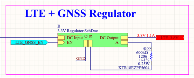
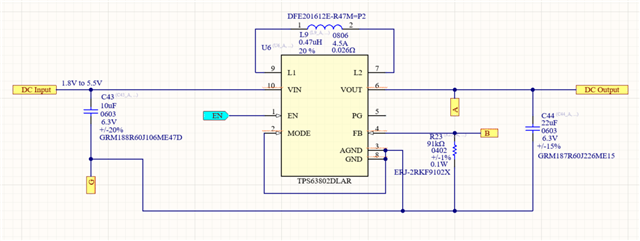
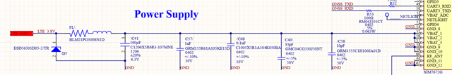
I suspect it's due to the voltage regulator on my LTE modem, as it's located next to the LTE modem. Due to this, I have placed a ferrite bead and multiple bypass capacitors at the output of the voltage regulator. I'm thinking it's somehow reducing the LTE modem's receiver sensitivity.

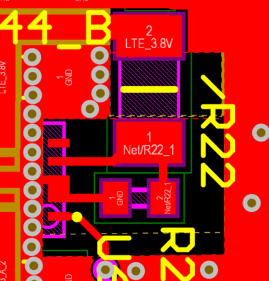
Attached is the circuit for your information.

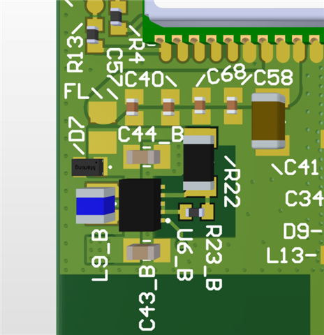
1) Is my assumption correct? You can see that the regulator is placed next to the LTE modem power supply input line, alongside numerous LTE modem bypass capacitors and ferrite beads. 

2) If yes, how do I solve this issue? Can I remove the TE modem's bypass capacitors and ferrite beads? I don't think it's required because the regulator is placed next to the power supply line. I'm also thinking it's cause of the regulator loop instability.

3) How do I verify the regulator causing the TIS issue failure? How do I verify the regular loop instability issue? 

  • Hi  Pragash,

    Ferrite bead is a good idea to filter out high frequency noise and blm21pg300sn1d is a good choice for 699MHz to 800MHz noise. I think it do help to improve.

    1)To be honest, i did not see a such high frequency noise generated by regulator before. Noise with maximum frequency i saw before is 350Mhz caused by LC oscillation, but i can not gurantee that 699MHz to 800MHz noise is not from our regulator.

    2)I am confused, why do you think remove beads and capacitors will help, it should be even worse, right? Do you think noise is coupled by space but not on board?

    3)Do you have power supply on hand, i think you can just disable the DCDC regulator and use power supply instead to see what will happen. Should not be caused bt instable loop because instable loop always cause some low frequency noise, such as Khz level.

    Regards

    Tao

  • 1)To be honest, i did not see a such high frequency noise generated by regulator before. Noise with maximum frequency i saw before is 350Mhz caused by LC oscillation, but i can not gurantee that 699MHz to 800MHz noise is not from our regulator.

    Answer: ok. 

    2)I am confused, why do you think remove beads and capacitors will help, it should be even worse, right? Do you think noise is coupled by space but not on board?

    Answer: I was assuming the regulator loop stability could have been disturbed by the ferrite bead placed too close to the DC-DC converter. that's why I was thinking removing it could help. 

    3)Do you have power supply on hand, i think you can just disable the DCDC regulator and use power supply instead to see what will happen. Should not be caused bt instable loop because instable loop always cause some low frequency noise, such as Khz level.

    Answer: ok. 

  • Hi Pragash,

    Ok, got it. actually you do not need concern about the affect of bead to loop stability.  Because  zero caused by bead and capacitor are much higher than bandwidth of regulatore. 

    Anyway, if you think necessary, you can try this, in case i made a mistake in my calculation...

    Regards

    Tao

  • ,

    You are right. I did a simple experiment here by replacing the ferrite bead with a zero-ohm resistor. I don't know how to measure a Bode plot on an oscilloscope, so I measure the Vpp of a DC-coupled voltage. I see a significant increase in the Vpp when I replace the ferrite bead with a zero-ohm. When I re-soldered the ferrite bead, the Vpp came down significantly. Is it a good way to make sure the loop is stable? I know loop stability might not be the cause of the TIS issue, but I just wanted to learn. 

  • Vpp (original with ferrite bead) - 90mV to 100mV

    Vpp (zero ohms replaced ferrite bead) - 100mV to 200mV

    Vpp (re-solder old ferrite bead) - 9mV to 13mV

    Vpp ripple might have been reduced because I solder better with a lot of solder on the pad than machine soldering? 

  • Hi Pragash,

    For loop stability analysis with oscilloscope, attachment should be a good guidance, please check application note attached.

    7457.slva381b.pdf

    Amazing that you got different ripple performance between original and re-solder. is it possible caused by some measure set-up?

    Regards

    Tao

  • I think it's because I solder better than the machine, as pads will have more solder when we hand solder. 

  • Hi ,

    We just bypassed the regulator, and our product indeed passed TIS. So this regulator generates the noise. You have seen the layout. Can you tell me why? 

  • Hi  Pragash,

    Yes, layout is well designed. that is sure. For a switching regulator, there always have some HF noise caused by switching edge.

    What make me feel curious is that why the bead did not work as expected because bead should have very good performance for this HF noise filter.

    Regards

    Tao

  • ,

    I think it's a layout issue. Once I confirmed it, I will let u know. 

  • Hi  Pragash,

    Is there any update for your case?

    Regards

    Tao

  • I think I need to shield the bottom layer, and that will fix the TIS issue. This ground cut goes all the way to the bottom of solid ground. I want to remove this ground cut at the bottom layer. This is for shielding from noise. Please let me know your thoughts. Only the bottom layer will not have the ground cut, but the rest of the layers will have it. 

  • Hi  Pragash,

    May i know why you think cut ground mentioned will help? from my side, i think it will not work because noise source and also coupling path should have nothing to do with FB net.

    Regards

    Tao

  • This is for shielding from noise. My question is, covering the ground cut at the bottom layer will have any impact on the regulator? We have a battery attached close to the PCB at the bottom layer anyway, so I don't think covering the bottom layer ground cut will have any negative impact on regulator performance. Please correct me if I'm wrong. 

  • Hi  Pragash,

    Agree that, no concern from my side about performance derating.

    Regards

    Tao