Tool/software:
Hello,
I have an issue where it looks like the output might be unstable, however when I simulate the compensation loop it shows that it should be stable.
Here are the current values that I am using:
Vin: 5V
Vout: 1.8V
Rcomp: 4.02k
CComp: 22nF
CHF: 1nF
Inductor: 2.2uH
CFF: 220pF
Output Cap: x3 330uF (ESR = 35mOhms) and a 10uF and a 100nF filter caps
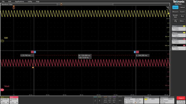
So when I simulate it looks like I have a cross over frequency of around 10kHz, a gain margin of 35.7dB and a Phase margin of 88 degrees.But when I power on the rail, it looks like the voltage oscillates between 2V to 3.5V.
I have tested turning on the 5V PoL with other PoLs and they are working properly (1.2V and 3.3V) and it is ok until I turn on the 1.8V PoL, The issue seems to be with the 1.8V PoL itself.
Some other observations:
1. The main supply for the system is 12V and it seems like the voltage output of the 5V drops
2. The switching node of the 5V PoL seems to be impacted by the instability of the 1V8 PoL. Im wondering if there is a weird current draw that is causing it to basically limit.
Let me know if I calculated the compensation loop incorrectly, or if you think there is a different issue.
Thank you
Albert