This thread has been locked.

If you have a related question, please click the "Ask a related question" button in the top right corner. The newly created question will be automatically linked to this question.

TPS54KC23: Coil whine in a 5V power supply

Part Number: TPS54KC23

Tool/software:

We are designing a power supply and have found a severe coil whine. After careful evaluation of our design, we realized there were two differences with the evaluation board: 

1. We did not make FB / GOSNS with a differential pair track. 


2. We substituted L2 resistor  

for: 
https://www.mouser.es/ProductDetail/Laird-Technologies/MGAH1004R68M-10?qs=By6Nw2ByBD3aICw2fHmD2Q%3D%3D


We are on the process of redesigning our board, and we will correct those two. Would it be safe to assume that coil whine is coming from either (or both) of those issues? 

Best regards, 

  • Hi Pablo, 

    The audible noise may be eliminated by switching to a Wurth inductor, as it offers a larger physical package size and a more rigid construction, which is likely to reduce vibration / lower resonance. Try that first, replace the inductor, and see if the audible noise goes away.

    Also, how does the switch node look? Are you running in Skip-mode or FCCM mode when the noise occurs? If it is happening at Skip-mode, the solution would be to operate in FCCM mode. 

    Thank you,
    Tomoya

  • Hello Tomoya, 

    I have substituted the inductor for a Wurth one and the noise is still there. Also I have changed some capacitors to tantalum and the noise was reduced a bit but never disappear.

    I have designed a custom PCB using the TPS54KC23RZR for a 12V input to 5V / 20A output application. I am experiencing a very loud, high-pitched audible noise (whining) from the converter stage, which seems to be related to instability.

    The noise can be slightly dampened by physically pressing down on the PCB near the output capacitors, which strongly suggests a mechanical vibration from a component.

    My Design Details:

    • Input Voltage: 8V - 16V (Nominal 12V)
    • Output Voltage: 5V
    • Max Output Current: 20A
    • Switching Frequency: 800 kHz (set by R_MSEL), FCCM mode, R_MSEL = 5k. 
    • Inductor (L5): 680 nH (Laird MGAH1004R68M-10)
    • Output Capacitance: 6 x 47µF MLCCs (282µF nominal)

    Feedback Resistors: R24 = 88.7k, R25 = 10k

    I have been investigating potential causes, and my main suspicion lies with my implementation of the feedback and ground sensing connections, especially when compared to the recommendations in the datasheet and the EVM layout. Could the audible noise be caused by an incorrect feedback sensing layout, specifically how the GOSNS (pin 13) is referenced?

    My Current Layout Implementation (see attached layout screenshot):

    • The GOSNS (pin 13) is connected to the main power ground plane (PGND) locally, near the IC.
    • The bottom of the feedback resistor R25 is also connected to this local PGND.
    • The feedback traces for FB (pin 14) and GOSNS (pin 13) do not form a differential pair routed to the point of load. It is a local sensing configuration.

    I have attached screenshots of my schematic, my PCB layout around the IC, and a reference layout from the datasheet for comparison.

    The datasheet explicitly recommends:

    1. "Route VOSNS+ and VOSNS- differentially to the load."
    2. "Single point AGND to PGND connection."

    My current layout does not follow the first recommendation. I suspect that by connecting GOSNS to the local, noisy PGND, I am introducing switching noise into the feedback loop, causing instability that manifests as audible oscillation.

    Before I proceed with a PCB redesign, could you please confirm if this incorrect GOSNS connection is a likely root cause for the severe audible noise I am experiencing? Would implementing a proper differential remote sense to the furthest output capacitor be the correct solution to stabilize the loop and eliminate the whining?

    Thank you for your time and expertise.

    Best regards,


    Images: 

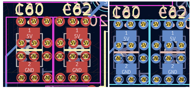
    Our PCB


  • Hi Pablo, 

    Single-ended Vout sensing is also acceptable, so I don't believe that is the cause of the audible noise. Ultimately, it depends on the amount of ripple present on the output and the type of components you're using. The mechanics of the PCB could also contribute to audible noise, as it can vibrate.

    I suspect the issue might be with your output capacitors. If you are using ceramic capacitors, could you provide the voltage rating and possibly the part number? It is possible that after DC biasing, the capacitance has dropped significantly. You might want to consider increasing the number of output capacitors to reduce the output ripple. Additionally, using smaller output capacitors could help mitigate the audible noise.

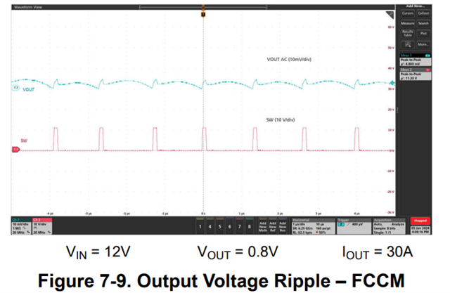
    It would be helpful to see the oscilloscope waveform of VOUT and the SW node as shown below. This will help us determine if the circuit is unstable.

    Thank you,
    Tomoya

  • Hi Tomoya,

    Thank you for your suggestions. I've performed the tests and have attached the waveforms you requested.

    Here are the key findings:

    • Capacitors: We are using 6x Murata GRM32ER71A476KE15L (47µF, 10V, X7R, 1210). We noted the EVM uses X6S, but we could not source a 10V-rated X6S part, as available options were 6.3V or lower.
    • Heavy Load (~80W): The SW node is clearly unstable and not periodic. Output ripple is high at ~400mVp-p.
    • Light Load (~8W): The SW node becomes periodic and the audible noise is much lower.
    • Mechanical Test:
      • Securing the PCB with standoffs (it was previously uneven on the surface) reduces the noise.
      • Our layout has 3 output caps on top and 3 on the bottom, directly opposite each other. Removing the 3 bottom capacitors also reduces the noise. We are unsure if this was due to the mechanical change or the electrical change from halving the output capacitance.

    These results raise the following questions:

    1. What is the more likely cause of the instability: the 680nH inductor value being too high, or insufficient effective capacitance?
    2. For our 5V output, would you recommend using a higher quantity (e.g., 10-12 units) or a 16V or 25V rating instead of 10V? Or both?
    3. Regarding our mechanical test: Could our specific layout with capacitors on both top and bottom layers directly opposite each other amplify the audible noise on the PCB?

    Thank you for your guidance.

    Best regards,

    Santiago S. and Pablo P., 

    Images: 


  • Hi Pablo and Santiago,

    What is the more likely cause of the instability: the 680nH inductor value being too high, or insufficient effective capacitance?

    Are you able to measure a Bode plot? Your phase margin might be too low, which could be causing instability. Try switching to RAMP2 or RAMP4 to see if that resolves the instability.

    For our 5V output, would you recommend using a higher quantity (e.g., 10-12 units) or a 16V or 25V rating instead of 10V? Or both?

    I believe your current setup is fine, but using a smaller capacitor size, like 0805 instead of 1210, could help reduce audible noise.

    Regarding our mechanical test: Could our specific layout with capacitors on both top and bottom layers directly opposite each other amplify the audible noise on the PCB?

    I'm not familiar with that specific issue, but you could reach out to the capacitor manufacturer for more information.

    I think the first step should be to address the instability problem, as doing so will likely also fix the audible noise issue.

    Thank you,
    Tomoya

  • Hello Tomoya!! 

    Thank you very much for your advices, we will implement everything we have learnt with this conversation. I was able to change the MSEL to 30.1k, which sets a switching frequency of 1400kHz and uses RAMP4. This has removed the noise even with high loads (80W). 

    Would this configuration be valid for us? Our ripple looks like this now: 


    Best regards, 

  • Hi Pablo,

    Would this configuration be valid for us?

    Yes, that is a valid option if you're willing to go to a higher switching frequency. 

    Thank you,
    Tomoya