


Other Parts Discussed in Thread: LM5170-Q1, , LM5171, TIDA-01040
Tool/software:
Dear team,
According to the internal material, LM5171-Q1 has capability to regulate output current in boost mode as well as buck mode, and this is the one of the biggest advantage against Lm5170-Q1. But I referred datasheet and could not find how to do it. I found the description about it is measuring HS-FET inductor current for IMON1/2 when boost by changing CONFIG register, but functional block diagram or current loop description pages looks it does not use that, which means CS amp input is used for current loop error.
#1. Would you please let me know how LM5171-Q1 estimate the output load current in boost mode?
#2. And would you please let me know where I can find the description that LM5171 "regulates" the output current when boost operation, not "monitor"?
#3. It is not related above questions but there is gap about I2C address between d/s page10(5.5 Electrical Characteristics - CONFIGURATIONS) and d/s page 15 (Table6-1). Which is correct address?
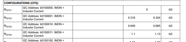
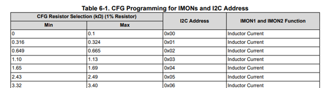
b0100000 = 0x20...
Best regards,
Yuto Kitamura


