This thread has been locked.

If you have a related question, please click the "Ask a related question" button in the top right corner. The newly created question will be automatically linked to this question.

TPS25730: External supply powering blockage

Part Number: TPS25730

Tool/software:

Hi TI support team,

I have some experiment to try with TPS25730DREFR. The idea is to use a external supply to power up instead of usb-c cable and vary a voltage level to see at what voltage a DUT will cut-off.

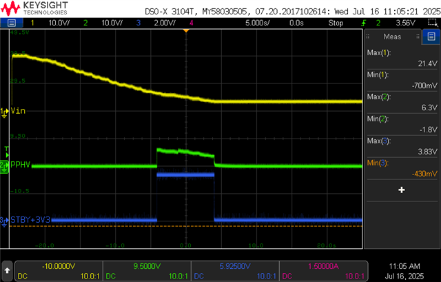
But my issue is the sink path is flow only in a range of around 3.6V-6.6V, refer to my result below even though my ADCIN config is 5V -20V and everything working just fine with a usb-c power adapter.

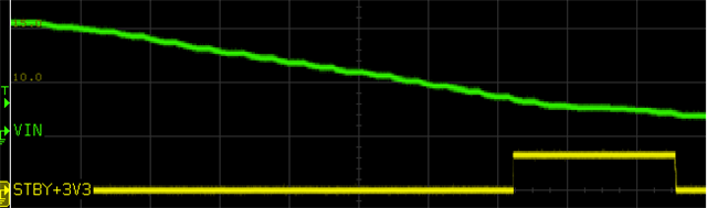
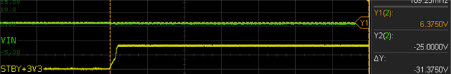
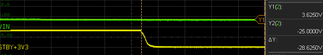
Note : STBY+3V3 is a VCC for local MCU.

My question is what could be a factor that block the internal FET and how can it's work at a 3.8V - 6.5V range?

Regards

Nitipong

  • Hi Nitipong,

    I'm not exactly sure what you are trying to test.

    You are measuring VBUS and VIN3V3, and slowly increasing the VBUS voltage?

    What are you expecting to see? Are you measuring the PPHV pin at all?

    The TPS25730 is looking for a type-C contract, which involves specific terminations at the CC line. Only applying a DC voltage from VBUS to GND is not enough to create a type-C contract.

    Thanks and Regards,

    Chris

  • Hi Chris

    Sorry for the confusion, This is a result measuring with PPHV.

    Please ignore a STBY+3V3 at VIN3V3 pin since I cut that trace already. STBY+3V3 is a source for local MCU which I use to see if DUT is on or not.

    I'm measuring it while decreasing a VBUS to the point where DUT will cut off. My current condition of CC pins are both pull up to a VBUS. I understand that the sink path should be disable by using only an voltage supplying only. 

    But my curiosity is why the PPHV is enable in a voltage range I refer above only.

    Regards

    Nitipong

  • Hi Nitipong,

    On initial connect, the TPS25730 first looks for pullup resistors on the CC line, and then will check the VBUS voltage to make sure it is in an expected range around 5-V.

    3.8V - 6.5V

    UVP at 5-V is expected to be around 3.9-V. At 5-V, seeing OVP trip at 6.5V is not unexpected either.

    Basically, on initial connect we expect to see CC voltage and VBUS around 5-V before we enable the power path. The 3.8-6.5V operational range is within the expected range for VBUS. Ideally, VBUS should be at 5-V though.

    Thanks and Regards,

    Chris