Tool/software:
Dear Sirs and Madams,
We obtained the LM74704Q1EVM and are evaluating its reverse current protection function.
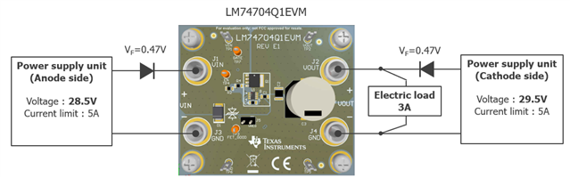
< Connection Diagram >
< Evaluation Procedure >
1. Set the output voltage of PSU(Anode side) to 28.5V and the current limit to 5A.
2. Set the output voltage of PSU(Cathode side) to 29.5V and the current limit to 5A.
3. Set the electronic load to 3A and turn it ON.
4. Turn on PSU(Anode side) and wait for the waveform to stabilize.
5. After turn on PSU(Cathode side), verify that the FET turns off and the current is cut off.
The result is as follows:
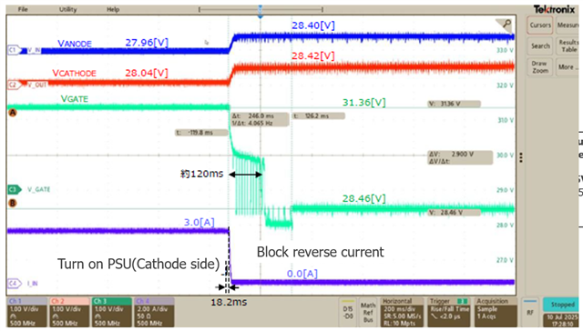
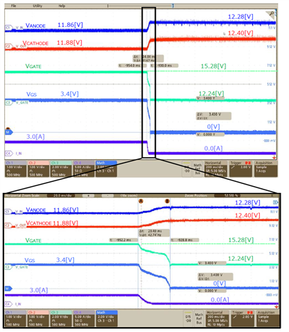
When we checked the operating waveforms, we could see that tReversedelay was significantly longer than the 0.75us specified in the datasheet.
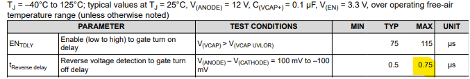
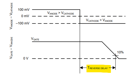
The data sheet specifies the condition of V(Anode)=12V, whereas we tested it at about 30V, so we suspect this difference is due to this. But is it really possible for such a big difference to occur?
Regards,
Masashi