This thread has been locked.

If you have a related question, please click the "Ask a related question" button in the top right corner. The newly created question will be automatically linked to this question.

TPS43061: Schematic Review Request for TPS43061

Part Number: TPS43061

Tool/software:

Dear TI Support Team,

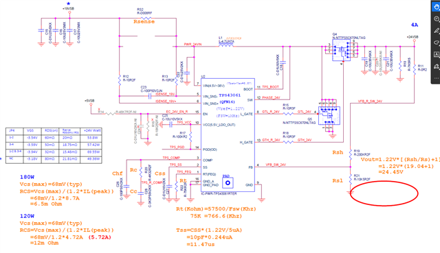
We are currently designing a system using the TPS43061 and would like to request your assistance in reviewing our schematic to ensure correct implementation and avoid any potential issues.

The schematic is attached for your reference.

Thanks!

  • Hi Tom,

    Thanks for using the e2e forum.
    Here are my comment on the design:

    1. They connect the VIN pin after the Rsense resistor. This means the supply current of the IC itself will be added to the sensed current.
    The impact of this toward the current limit is probably barely visible, but in general it is recommended to connect VIN directly to the supply (+19VSB rail)

    2. There are only 20uF output capacitance. Is there additional bulk capacitance that is not seen in this picture?
    If not, I would highly recommend to increase output capacitance to stabilize the output voltage. 20uF is not sufficient for these power levels.

    The rest of the design look okay to me.

    Best regards,
    Niklas

  • Hi Niklas,

    Thank you for your suggestion. The output capacitor is currently only 20 µF.

    Could you please advise how much additional capacitance I should add?

    Best regards,
    Tom

  • Hi Tom,

    The required capacitance depends on your design goals.
    In general, more capacitance means less output voltage ripple.

    To give a reference, our TPS43061 EVM has a output power rating of 30W and uses 40uF output capacitance.
    The waveform shows an AC output voltage ripple of ~ 100mV.
    As your design has higher power ratings, it might require more capacitance to achieve the same Vout ripple.
    For calculating the minimum required capacitance, I can recommend our quickstart calculator tool:
    https://www.ti.com/tool/download/SLVC471

    Also, if you expect strong load transients in your application, I would also recommend to place the footprint for a large bulk capacitor, so you can add further capacitance on bench without design change if the measurements show large Vout over-/undershoots.

    Best regards,
    Niklas