This thread has been locked.

If you have a related question, please click the "Ask a related question" button in the top right corner. The newly created question will be automatically linked to this question.

TPS7B7702-Q1: Short to GND Test Observation

Part Number: TPS7B7702-Q1
Other Parts Discussed in Thread: TPS7B7702,

Tool/software:

Hello Team,

We are doing the below test case for Power line generated/given by TPS7B7702Q part.

1) Setup is made as per the shown Block diagram


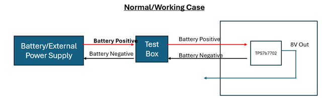
2) When the GND Between test box and Battery is removed, DUT/Silverbox is OFF


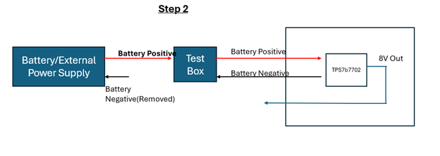
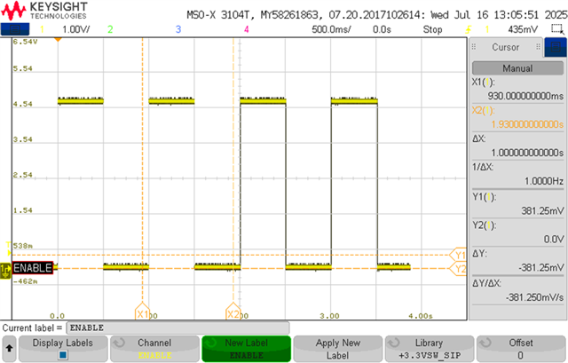
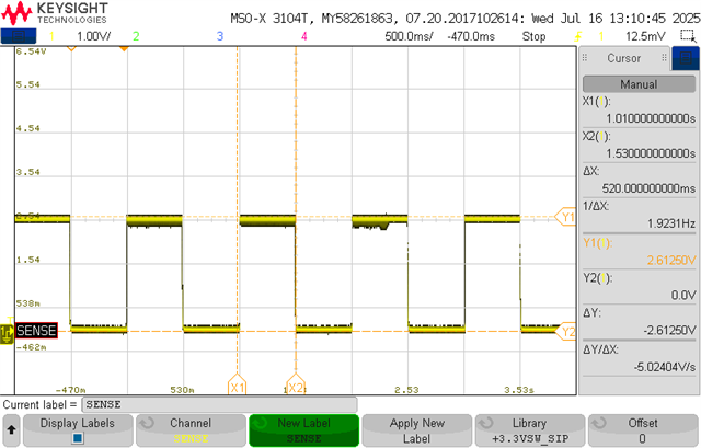
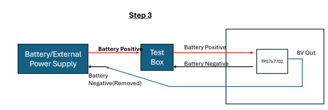
3) When the TPS7B7702 Output PowerLine is connected to Battery GND , the IVI turn ON (Do not know why/how)

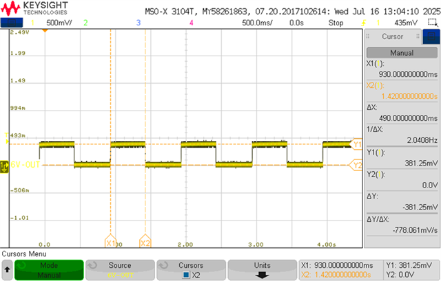
4) When the short is removed , and Battery negative is connected back to test box negative, we see that O/P of IC is 0V (Seeing 350mV and 0V periodically)

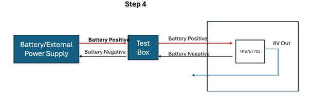
When I changed it with new IC, the O/P voltage is coming correctly.

Can you tell me what can be the reason why IVI turn ON when GND is connected on Output of TPS7B7702? Why is the IC getting damaged?

Thanks and Regards

Sumit

  • Hi Sumit,

    When the battery negative is disconnected, the part's ground may be floating at the battery positive. Connecting the output node to the battery negative could violate the -0.3V minimum abs max rating. Behavior after that would be out of spec. 

    How frequently is going between 350mV and 0V? Is it pulsing or oscillating/what does the waveform look like?

    Can you tell me more about the test box? Are you attaching the battery negative directly to a chassis ground, etc?

    Best,

    Gregory Thompson

  • Hello Gergory,

    For better understanding please consider Battery as an external Power supply unit only with which we are testing.
    Below are the capture for Vout of TPS7B7702.


    In the damaged IC, i am also seeing EN pin continuously going toggling and the IC is also HOT.


    Below is the capture of SENSE PIN


    Below are my queries->

    Your comment-> Connecting the output node to the battery negative could violate the -0.3V minimum abs max rating. Behavior after that would be out of spec. 

    Query-> Battery negative is external Power supply GND. How is 0V out of spec for -0.3V

    Query-> Is there any reason how when OUT pin is connected to GND we see System turning ON, how is the GND path for system getting completed?


    Testbox GND and System/Silverbox GND is same , there are no 2 different GNDs. Only 1 GND is present which comes from Test box.

  • Hi Sumit,

    Thank you for the further info. It seems like something has happened to drive the EN pin to create this behavior and (judging by the SENSE PIN value) the device is hitting current limit when on.

    Response 1-> 0V is only out of Abs Max for -0.3V when the part's ground is >0.3V. This can happen when a ground path has been disconnected, but I am not certain this is what's happening here, especially if the testbox is grounded.

    Response 2-> I'm not quite sure where the GND path is with the information I have at the moment. Does it stay on steady state or only turning on for a brief period of time?

    Question A-> What is the voltage at the external supply positive and negative terminal (relative to system ground) especially when you connect output directly? Can the external supply float? If it can, the rails can be pushed (relative to system ground) out of Abs Max as it tries to regulate itself. That's a known concern when we use a similar technique is used to measure quiescent current.

    Question B-> What does the actual test setup for the TPS7B7702-Q1 look like inside the testbox?. Is it just a mounted EVM, how is the device configured, etc.?

    Question C-> The TPS7B7702-Q1 has two independent outputs, how is the other output configured and how does it behave after the part has been damaged?

    Best,

    Gregory Thompson

  • Hello Gregory,

    Below are response

    Question A-> What is the voltage at the external supply positive and negative terminal (relative to system ground) especially when you connect output directly? Can the external supply float? If it can, the rails can be pushed (relative to system ground) out of Abs Max as it tries to regulate itself. That's a known concern when we use a similar technique is used to measure quiescent current.
    Response- There is only one ground for full system, i.e. Power supply negative.is the DC Ground. to DUT/PCBA.

    Question B-> What does the actual test setup for the TPS7B7702-Q1 look like inside the testbox?. Is it just a mounted EVM, how is the device configured, etc.?
    Response-> Testbox is just a switch Box kind of thing to manually Switch ON/OFF the power supply for the DUT. DUT is the board which has TPS7B77702 IC.
    I also tried by eliminating the test box and directly connecting external power supply to DUT. When the positive of power supply is connected to DUT and negative of power supply is connected to DUT-> Normal operation is observed..
    When the negative from power supply is removed from DUT and Output power rail of TPS7B7702 is SHORTED to GND , I see device booting up (which is not expected- not sure how it gets Ground path). After this the IC is not functioning properly. Is the device allowed to handle this scenario.
     

    Question C-> The TPS7B7702-Q1 has two independent outputs, how is the other output configured and how does it behave after the part has been damaged?
    Response- Other channel