This thread has been locked.

If you have a related question, please click the "Ask a related question" button in the top right corner. The newly created question will be automatically linked to this question.

TPS92520-Q1: Power dissipation and application, also contain TPS92682

Part Number: TPS92520-Q1
Other Parts Discussed in Thread: TIDA-050030, TPS92682-Q1

Tool/software:

Hello Expert

I have a Headlight  quote project which we want to use 1*TPS92682 with 2 phase CV boost and 3* TPS92520 CC buck .

Related requirements as below shown:

For TPS92682 2* phase CV boost:

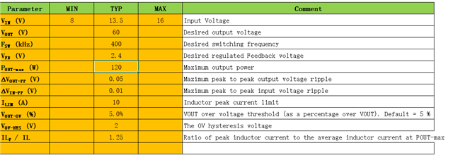
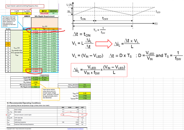
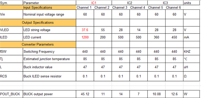
For TPS92520 CC buck: 

Input voltage: 60V

Output voltage range: 2-55V

Output current rang: 0.1-1.5A

1 channel need to support Max.45W 37.6V/1200mA

other 5 channel need to support Max. 30W。

totally allowed output power Max. 100W

I list the possible power dissipation distribution for your reference,

my question:

1)  CV boost output 60V, CC up to 55V, is it OK or not?

2)  CC  chip IC1 one channel 45W, tot 56W, is it OK or not?

3)  Do you have power dissipation calculation sheet without PROT contain TPS92682 and TPS92520 can share to me?

4) Is it possible to use TIDA-050030 120W Dual-Stage Matrix Compatible Automotive Headlight ECU Reference Design for quickly quote EBOM?

5) Do you have detail 2 phase CV boost step by step application calculation method for external E-parts share to me ?

6) which is max. allowed power dissipation for TPS92682 2phase CV and TPS92520?

other unclear information, let me know.

Thanks in advance!

  • Hello Ping,

    Please search the E2E database before posting questions.  There are lots of common questions that have already been answered.  The post below has a power loss calculation sheet for a TPS92682 in a two phase, CV mode and it has two TPS92520 channels that include efficiency for each stage and for each device.  

    https://e2e.ti.com/support/power-management-group/power-management/f/power-management-forum/1359113/tps92520-q1-about-the-tps92520-efficiency?tisearch=e2e-sitesearch&keymatch=TPS92520-Q1%2520efficiency%2520calculations# 

    1.  I can't answer this without knowing the desired switching frequency.  Do you have a specific desired switching frequency?  There is a min off time which sets that max duty cycle.  55V/60V = 91.67% duty cycle.  That should be ok at lower switching frequencies like 440 kHz.  You also have to make sure you meet min sensed ripple spec of 20mV, which is dependant on peak to peak ripple current in the inductor and the current sense resistor used.  ripple current is dependant on lots of variables too.  current sense resistor selected is based on max current supported.  If you need 1.5A then you would need 0.1 ohms for current sense resistor.    I did a quick calculations based on some assumptions, and it looks like you are marginal at the 59Vin and 55Vled and are marginal at 2Vled for all input voltages.    

    2.  The device can handle the output power but it really is a question of heat management.  Can you provide enough heat sinking such that it doesn't exceed the max junction requirements of our device at those high loads and with a hot ambient environment like 105C.  .  You will need to minimize the gap between top side thermal pad of our device and make sure to use low thermal resistance gap filler.  

    3.  What is PROT?  The power loss calculation sheet is in the previous post.  You can down load it.  

    4.  That is up to you.  The BOM is on the TIDA-050030 page at TI.com.  I think it is a good starting point, but I don't know what else you plan to do on the ECU that would affect the cost of the solution.  There are lots of things that can drastically change the cost of that board like connectors, so you need to make those decisions on what to include and what not to include in the cost analysis.  

    5.  There is a calculation sheet on the TPS9268-Q1 page.  https://www.ti.com/tool/download/SLUC690 There are several of them and you should go to the main page to look for tools, reference designs, EVMs, User's Guide, Datasheets, etc..

    6.  I can't give you a simple number because it depends on operating conditions, heat sinking, component selection, and lots of other variables etc.  Can you make a two phase boost output 130W, sure, but you have to design it properly.  You need to select components to ensure that you don't expose those parts to temperatures outside its max operating junction and that depends on heat sinking and ambient environment specifications, and operating conditions.  The TPS92682-Q1 is a controller so that shouldn't have that much power loss.  Most of the losses are in the power components such as switching fet, diode, inductors, etc.  The TPS92520 can output a lot of power but again it then becomes a functions of thermal management such that you don't exceed our max operating junction temperature.  We have output 60W in one IC before but again you need good thermal management. 

    -fhoude