This thread has been locked.

If you have a related question, please click the "Ask a related question" button in the top right corner. The newly created question will be automatically linked to this question.

UCD3138CC64EVM-030: PSFB Cannot configure board, change frequency, or see any DPWM outputs

Part Number: UCD3138CC64EVM-030
Other Parts Discussed in Thread: UCD3138PSFBEVM-027, UCD3138, USB-TO-GPIO2

Tool/software:

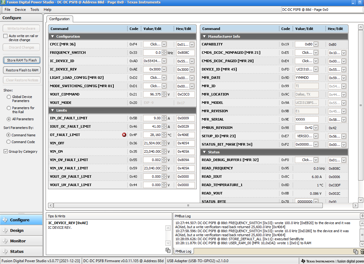
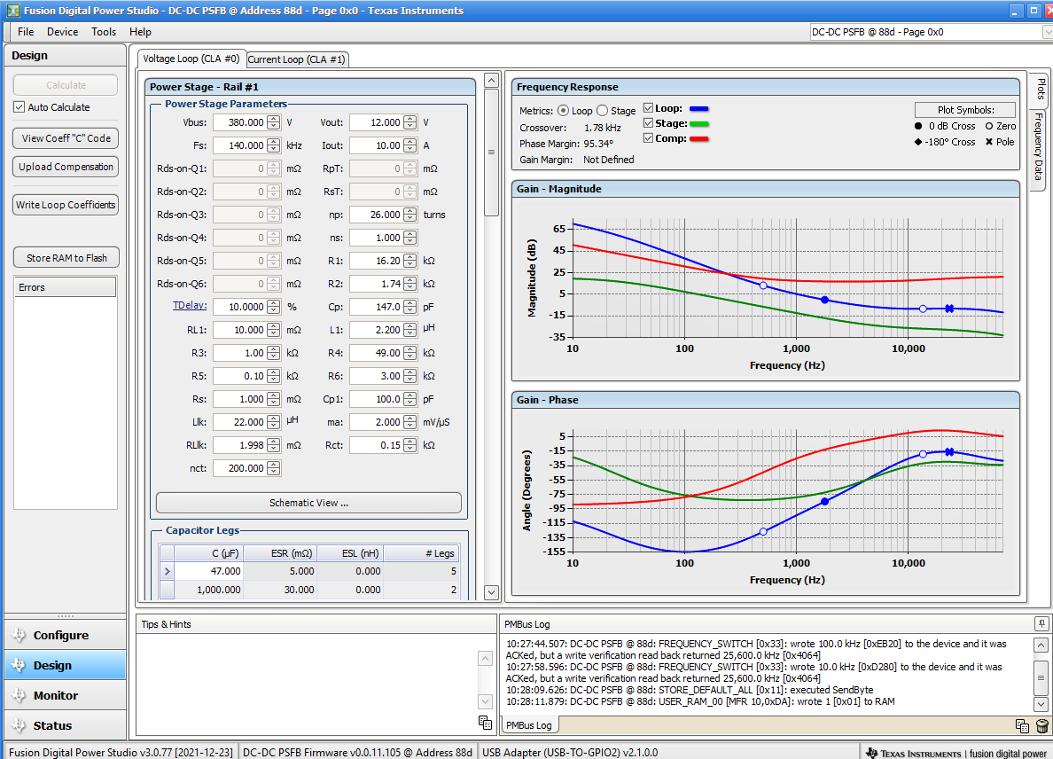
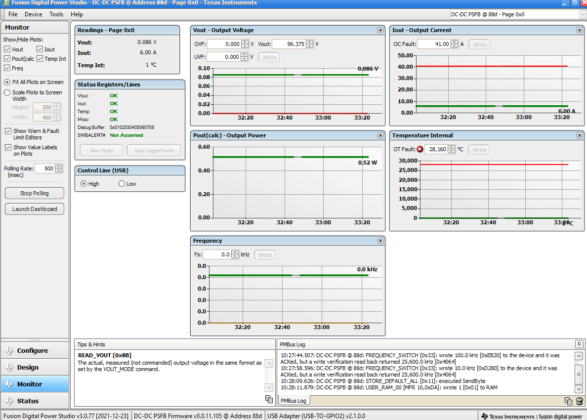
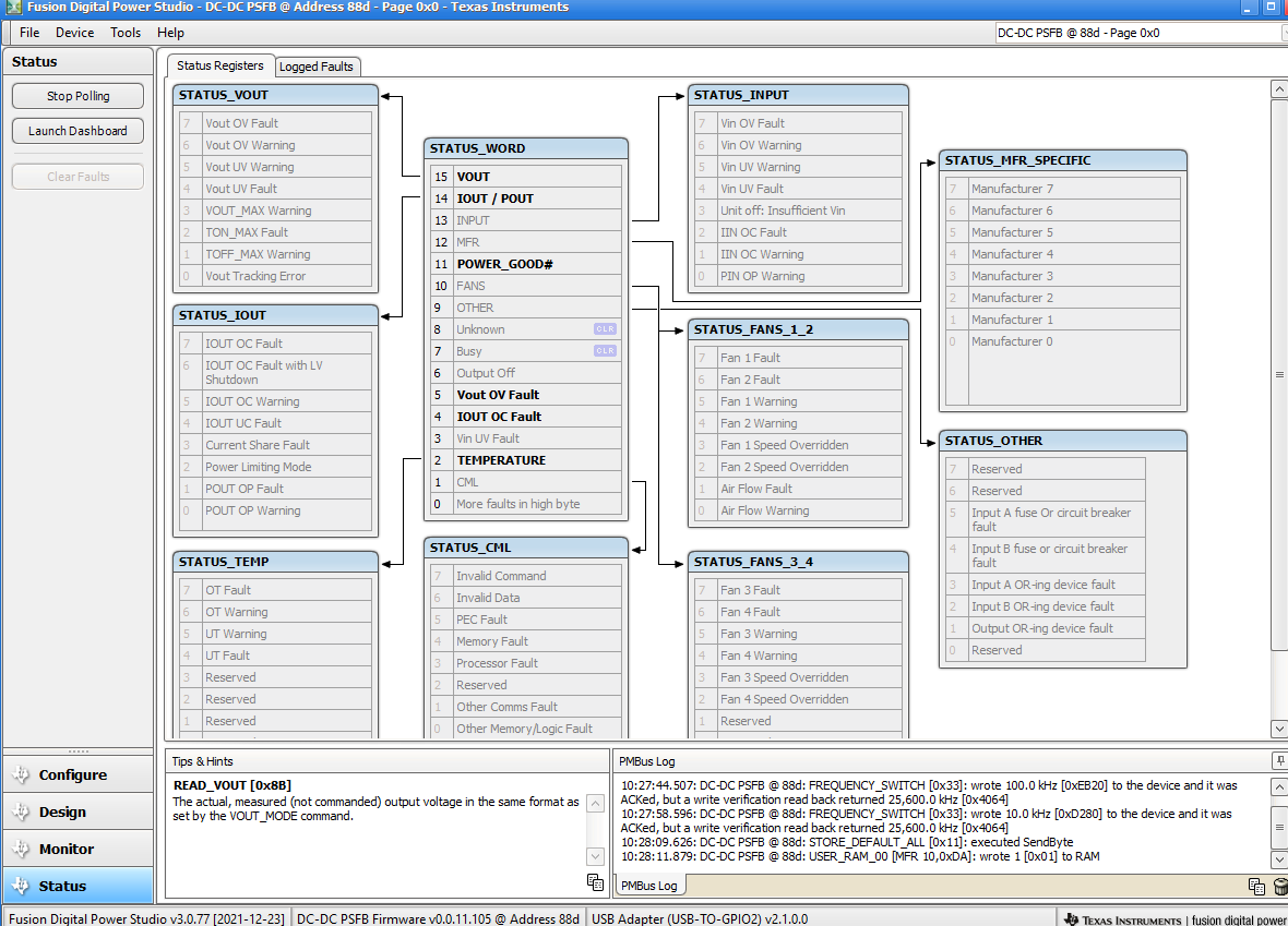
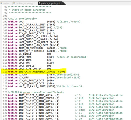
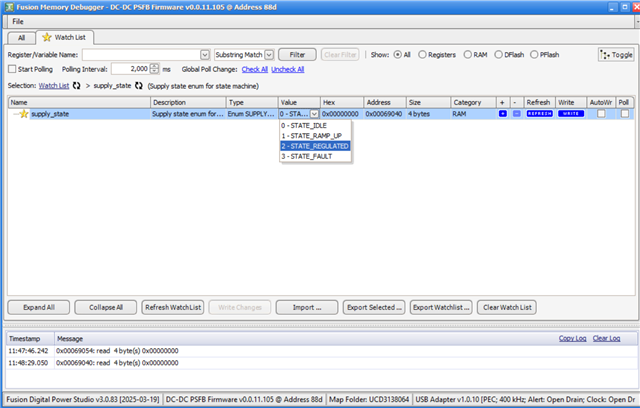
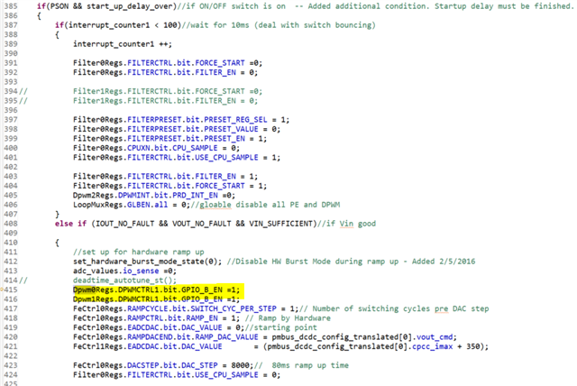
I have the UCD3138CC64EVM-030 connected to my PC via the PMbus and 2022 USB Interface Adapter with no external supply and not connected to any power stage. Fusion Digital Power Studio (with the PSFB firmware from TI - unaltered) shows 32V Vout (even though the configure tab setting is at 96V), 6A Iout, but 0kHz frequency. The Status tab is showing Vout 0V fault, Iout 0C Fault, TEMPERATURE, POWER_GOOD#, IOUT/POUT and VOUT under STATUS_WORD. The design tab has the default values (though would this matter as there is no power stage attached?), and Fs and Vout do not match the configure tab. If I try to change the VOUT_COMMAND value it just goes to 0 though Vout never changes from 32V. I can temporarily change the FREQUENCY_SWITCH (only to 25.6kHz and nothign else) and write to hardware but this resets to 0 if the device is reset, removed or "Store RAM to flash" is pressed. What I would like to do at this moment is be able to change the desired output voltage but especially frequency, and observe the DPWM outputs via an oscilloscope. Is the reason I cannot change the frequency because it is not attached to a power stage? Or because it has no external supply? How could I test it without a power stage simply in order to view the DPWM waveforms and frequencies. Thanks.

  • Hi Adam,

    I think what would help is to understand a generic state machine that is inside an SMPS controller. When you are controlling an SMPS using the UCD3138x controllers, you would typically have a state machine with the 4 states: IDLE, RAMP_UP, REGULATION and FAULT. Most designs may include more states but these are the 4 basic states that we use. See the image for a generic state machine diagram.

    This state machine is the foundation for most designs using the UCD3138x, including the PSFB topology. This is typically implemented using the standard interrupt, which typically triggers ~10kHz (see the T16 timer section). A key feature of this state machine is that it allows the UCD3138x to easily implement a soft start feature. We do not want the SMPS to immediately power on. Once an input voltage threshold has been reached, we will ramp the output voltage so we avoid a large overshoot like the one below. This ramp can be easily configured in the code and is highlighted in section 3.3 of the UCD31xx Technical Reference Manual page 118.

    Below is an example state machine operation over time. If the blue line is our Target Vout (our Vref), the green line is our Vin, the red line is our actual Vout, and we have a Vin_on threshold = 28.5V, then the SMPS will change between the 4 states accordingly. 

    The issue with only using the control card is that likely no VIN_ON Threshold has been reached and thus, you are stuck in the IDLE state. You can either remove the state machine and go directly to the REGULATION state or simulate a voltage onto your adc to trigger the VIN_ON Threshold.

    Below is the idle_state_handler() function in the UCD3138FW-PSFB  example code standard_interrupts.c file. As you can see, the idle state does not move into the ramp state unless there are no faults and we are above the VIN_ON threshold. 

    inline void idle_state_handler(void)
    {
    	volatile int32 temp;
    
    	/*The following start up delay was added since the 12 V bias has a long delay before
    	presenting a valid 12 V to the gate drive circuitry. This delay insures that there is
    	enough time for the bias to power up and stabilize prior to attempting any turn on.*/
    	if (!start_up_delay_over)
    	{
    		if (count == count_end)
    		{
    			start_up_delay_over = 1;
    		}
    		else
    		{
    			count++;
    		}
    	}
    
    	if(PSON && start_up_delay_over)//if ON/OFF switch is on  -- Added additional condition. Startup delay must be finished.
    	{
    		if(interrupt_counter1 < 100)//wait for 10ms (deal with switch bouncing)
    		{
    			interrupt_counter1 ++;
    
    			Filter0Regs.FILTERCTRL.bit.FORCE_START =0;
    			Filter0Regs.FILTERCTRL.bit.FILTER_EN = 0;
    
    //			Filter1Regs.FILTERCTRL.bit.FORCE_START =0;
    //			Filter1Regs.FILTERCTRL.bit.FILTER_EN = 0;
    
                Filter0Regs.FILTERPRESET.bit.PRESET_REG_SEL = 1;    
    			Filter0Regs.FILTERPRESET.bit.PRESET_VALUE = 0;
    			Filter0Regs.FILTERPRESET.bit.PRESET_EN = 1;
    			Filter0Regs.CPUXN.bit.CPU_SAMPLE = 0;
    			Filter0Regs.FILTERCTRL.bit.USE_CPU_SAMPLE = 1;
    
    			Filter0Regs.FILTERCTRL.bit.FILTER_EN = 1;
    			Filter0Regs.FILTERCTRL.bit.FORCE_START = 1;
    			Dpwm2Regs.DPWMINT.bit.PRD_INT_EN =0;
    			LoopMuxRegs.GLBEN.all = 0;//gloable disable all PE and DPWM
    		}
    		else if (IOUT_NO_FAULT && VOUT_NO_FAULT && VIN_SUFFICIENT)//if Vin good
    
    		{
    			//set up for hardware ramp up
    			set_hardware_burst_mode_state(0); //Disable HW Burst Mode during ramp up - Added 2/5/2016
    			adc_values.io_sense =0;
    //			deadtime_autotune_st();
    			Dpwm0Regs.DPWMCTRL1.bit.GPIO_B_EN =1;
    			Dpwm1Regs.DPWMCTRL1.bit.GPIO_B_EN =1;
    			FeCtrl0Regs.RAMPCYCLE.bit.SWITCH_CYC_PER_STEP = 1;// Number of switching cycles pre DAC step
    			FeCtrl0Regs.RAMPCTRL.bit.RAMP_EN = 1; // Ramp by Hardware
    			FeCtrl0Regs.EADCDAC.bit.DAC_VALUE = 0;//starting point
    			FeCtrl0Regs.RAMPDACEND.bit.RAMP_DAC_VALUE = pmbus_dcdc_config_translated[0].vout_cmd;
    			FeCtrl1Regs.EADCDAC.bit.DAC_VALUE  		= (pmbus_dcdc_config_translated[0].cpcc_imax + 350);
    
    			FeCtrl0Regs.DACSTEP.bit.DAC_STEP = 8000;//  80ms ramp up time
    			Filter0Regs.FILTERCTRL.bit.USE_CPU_SAMPLE = 0;
    		
    			Dpwm2Regs.DPWMEDGEGEN.bit.EDGE_EN = 1;
    
    			LoopMuxRegs.GLBEN.all = 0x70F;//global enable all Front_ends and DPWMs
    
    			LoopMuxRegs.EXTDACCTRL.bit.DAC2_SEL = 4;   //voltage loop
                #if   defined(UCD3138128) || defined(UCD3138A64) || defined(UCD3138128A) || defined(UCD3138A64A)
    			  LoopMuxRegs.APCMCTRL.bit.PCM_FILTER_SEL =0; //select filter0
    			#elif defined(UCD3138) || defined(UCD3138A) || defined(UCD3138064) || defined(UCD3138064A)
    			  LoopMuxRegs.PCMCTRL.bit.PCM_FILTER_SEL =0; //select filter0
    			#endif
     			Filter0Regs.FILTERCTRL.bit.KI_STALL =0;


    			MiscAnalogRegs.GLBIOVAL.all |= MASK_OR_CTRL;//turn off the oring FET
    
    			supply_state = STATE_RAMP_UP;
    			preset_filter0(0x0); //7FFFFFF
    			preset_filter1(0x7FFFFF); //7FFFFFF
    			FeCtrl0Regs.RAMPCTRL.bit.FIRMWARE_START = 1; //Initiate soft start ramp 
    			FeCtrl1Regs.RAMPCTRL.bit.FIRMWARE_START = 1; //Initiate soft start ramp 
    
    			LoopMuxRegs.GLBEN.all = 0x70F;//global enable all Front_ends and DPWMs
    
    
    			disable_fast_interrupt();
    			temp = FaultMuxRegs.FAULTMUXINTSTAT.all; 		//read to clear the interrupt flag
    			FaultMuxRegs.ACOMPCTRL0.bit.ACOMP_B_INT_EN = 1; //enable ACOMP-B interrupt
    			FaultMuxRegs.ACOMPCTRL2.bit.ACOMP_E_INT_EN = 1;	//enable ACOMP-E interrupt
    			Dpwm2Regs.DPWMINT.bit.PRD_INT_EN =1;
    			temp = FaultMuxRegs.FAULTMUXINTSTAT.all; 
     			enable_fast_interrupt(); //make sure fast interrupt is enabled for shutdown
    
    			fault_type = 0;
    			fault_flag =0;
    			cp_flag =1;
    			cc_flag =0;	
    			vv_flag =0;
    			cv_trans_flag =0;
    			timer_interrupt_temporary_1 =0;
    			timer_interrupt_temporary_2 = 0;
    			cc_counter =0;
    			cc_shutdown =0;
    			current_share_temp =100;
    			sr_counter =0;
    			sr_on =0;
    
    #if    defined(UCD3138) || defined(UCD3138A) || defined(UCD3138064) || defined(UCD3138064A)
    
    		}
    	}
    	else
    	{
    		interrupt_counter1 = 0;
    
    #elif  defined(UCD3138A64) || defined(UCD3138128) || defined(UCD3138A64A) || defined(UCD3138128A)
    
    		        oring_on =0;
    				oring_counter =0;
    				currentsharing_threshold = CURRENT_SHARING_THRESHOLD;
    				currentsharing_backstep =16;
    				LoopMuxRegs.LLCTRL.bit.LL_EN = 1;
    
    				FaultMuxRegs.DCOMPCTRL0.bit.COMP_EN =0;
    				FaultMuxRegs.DCOMPCTRL0.bit.CNT_CLR =1; //clear DCOMP reading
    				FaultMuxRegs.DCOMPCTRL0.bit.CNT_CLR =0;
    
    			}
    		}
    		else
    		{
    			interrupt_counter1 = 0;
    			FaultMuxRegs.DCOMPCTRL0.bit.COMP_EN =0;
    #endif
    	}
    }

    To find the default VIN_ON threshold, see the system_defines.h file and the pmbus_topology.h file. Based on the code, the default VIN_ON threshold is if the UCD3138x detects an input voltage of 346V. The comment says this corresponds to an ADC count of 2,674. Since the UCD3138x 12-bit ADCs encode 0V - 2.5V as a count of 0 - 4096, that corresponds to a voltage of ~1.63V. Checking the UCD3138PSFBEVM-027 schematic shows that AD08 is sensing the input voltage. So, if you apply a >1.63V to the AD08 pin, then the state machine should move from the IDLE state to the RAMP_UP state. If you monitor the state_machine variable in the memory debugger, then you should be able to tell what state you are in.

    //Vout measurement defines
    #define VOUT_FULL_RANGE (25) //full range of ADC for VOUT
    #define VOUT_POWER_GOOD_ON ((int32)((11.5*4096)/VOUT_FULL_RANGE))//11.5V
    #define VOUT_POWER_GOOD_OFF ((int32)((10*4096)/VOUT_FULL_RANGE))//11V
    //#define VIN_GOOD (2674)//ready to turn on
    //#define VIN_BAD (2630)//vin is low to turn off
    //#define VIN_ON (2674)//ready to turn on
    //#define VIN_OFF (2630)//vin is low to turn off
    //#define UVIN_NO_FAULT (adc_values.vin_mon > VIN_ON)
    //#define UVIN_FAULT (adc_values.vin_mon < VIN_OFF)
    #define VIN_SUFFICIENT (adc_values.vin_mon > pmbus_dcdc_config_translated[0].vin_on )
    #define VIN_NOT_SUFFICIENT (adc_values.vin_mon < pmbus_dcdc_config_translated[0].vin_off)
    #define VIN_UV_FAULT (adc_values.vin_mon < pmbus_dcdc_config_translated[0].vin_uv_fault_limit)
    #define VIN_OV_FAULT (adc_values.vin_mon > pmbus_dcdc_config_translated[0].vin_ov_fault_limit)

    //DC/DC configuration
    #define VOUT 				(6080) //(6100) //(6144)
    #define VOUT_OV_FAULT_LIMIT (7168)
    #define IOUT_OC_FAULT_LIMIT (41) //(38)
    #define TEMP_OT_FAULT_LIMIT (110)
    #define IIN_OC_FAULT_LIMIT	(9) //
    #define MODE_SWITCH_HI_UPPER (0<<14)
    #define MODE_SWITCH_HI_LOWER (0<<14)
    #define MODE_SWITCH_LOW_UPPER (0<<14)
    #define MODE_SWITCH_LOW_LOWER (0<<14)
    #define TURN_ON_THRESHOLD	(60000) //2000
    #define TURN_OFF_THRESHOLD	(40000) //1000
    #define LL_ENABLE			(0)
    #define CPCC_PMAX			(360)  //303W on measurement
    #define CPCC_IMAX			(33)
    #define CPCC_TON			(100)
    #define CPCC_ENABLE			(0)
    #define CPCC_TIME_OUT_EN	(0)
    #define SWITCHING_FREQUENCY_DEFAULT (140)
    #define VIN_ON              (346)//translated(2674)
    #define VIN_OFF             (340)//translated (2630)
    #define VIN_OV_FAULT_LIMIT  (410)
    #define VIN_UV_FAULT_LIMIT  (346)
    #define VOUT_UV_FAULT_LIMIT (5376)//10.5V in Linear16

    Regards,

    Jonathan Wong

  • Hi Jonathan, 

    Thanks for your reply, that was very helpful. I understand that with no Vin the device will remain in IDLE state and hence produce no waveforms on the DPWM pins. My issue is that I am unable to use the configure menu and cannot change the desired Vout or switching frequency. When I try to set a value of VOUT_COMMAND it reverts to zero, same for FREQUENCY_SWITCH. FREQUENCY_SWITCH will sometimes allow 25.6kHz (and nothing else) but only temporarily. How do I go about configuring these parameters so that when I do connect an input voltage it produces the desired result?

    Thanks.

  • Hi Adam,

    At this point, I would need more information or background on your setup. Can you please share some screenshots of the memory debugger and the Fusion Studio Online? Can you also please share some waveforms on the oscilloscope? Lastly, can you also share a picture of your lab test setup?

    Regards,

    Jonathan Wong

  • Hi Jonathan,

    For the physical setup I have the board connected to my PC via the PMbus adapter, with J2 and J6 jumper headers (the PC is supplying the power to the board. Board light is green so power OK). I don't have any power stage attached or oscilloscope connected as for now I am just trying to configure the board. I have attached screenshots of Fusion Digital Power Studio. All of the settings are the default of the TI PSFB firmware. I am unable to change any of the configure settings as they revert to 0 when I try to change them ("wrote _ to the device and it was ACked, but a write verification read returned _"). The frequency and voltage are the main ones I am trying to change but it does not allow me to write the changes to hardware or store RAM to flash. I also cannot change the OV/OC fault limits as they also revert to 0. If you need any other screenshots or information I will be happy to provide.

    Thanks, Adam.


  • Hi Adam,

    It looks like your Fusion GUI is not communicating properly with the UCD3138 via PMBus. You can see that values such as your VIN = 21,504, which is way off.

    Are you using the USB-TO-GPIO2 (2022) adapter? We have seen some issues with this adapter sending wrong information to the GUI. If you can find a USB-TO-GPIO (2006) adapter, then that may work better. 

    I see you are using Fusion Digital Power Studio v3.0.77. Try installing this unreleased version of the Fusion Digital Power Studio v3.0.83: https://e2e.ti.com/cfs-file/__key/communityserver-discussions-components-files/196/TI_2D00_Fusion_2D00_Digital_2D00_Power_2D00_Studio_2D00_3.0.83.test. I renamed the file as ".test." so it can be uploaded. Just rename the extension to ".exe" to install.

    Regards,

    Jonathan Wong

  • Hi Jonathan,

    Thank you for all your help so far. The new version seems to work much better, as I can now change all the configuration setting, except the frequency which  is now fixed at 140kHz (which is better than zero but I still need to change it). I don't think the adapter is the issue as when I tap the pins on the board I can see spikes and noise on the graphs. I will try probing the boad and giving it an input. Could you confirm exactly which pins need connections in order for the board to function?

    Thanks,
    Adam.

  • Hi Adam,

    I think your connection to the UCD3138x is fine. The PMBus adapter is all you need to connect the USB-TO-GPIO2 to the UCD3138 control card.

    The Fusion GUI v3.0.83 is an updated GUI that is supposed to fix the miscommunication between the USB-TO-GPIO2 and the Fusion GUI. This version should have fixed all of your issues. 

    Can you try using other UCD3138x example firmware to see if you can change the frequency using the GUI? For example, the UCD3138 FW SDK (https://www.ti.com/tool/UCD3138_FW_SDK) has other example topologies. 

    In the meantime, you can manually change the switching frequency by changing the value in the code. This is found in pmbus_topology.h. You can build the project and flash the newly generated .x0 file onto your UCD3138x using the UCD3xxx Device GUI. 

    Regards,

    Jonathan Wong

  • Hi Jonathan,

    I have the UCD3138CC64EVM-030 connected to the UCD3138PSFBEVM-027 and the computer via the PMBus. Can I clarify if the 12V external connection is required as long as the computer is connected? 

    I am also struggling to force a Vout into the control card (just in order to 'trick' the controller into thinking it should move out of the IDLE state), as I'd ideally like to move the board into the regulated state (and be able to probe it) without having to apply the full 400V input.

    Finally, what is the range of frequencies the setup can operate at? Ideally I would like to sync the switching frequency, meaning it can vary during operation.

    Thanks,
    Adam.

  • Hi Adam,

    If you are connecting your control card onto your PSFB EVM motherboard, then I would recommend that you supply power to the UCD via the motherboard instead of via the PMBus. We have had issues when you try to supply power via the PMBus while controlling the motherboard. The issue is likely due to grounding mismatch between your laptop and the PSFB EVM motherboard. If you supply power via the motherboard, then the aux flyback should start operating at ~100Vin to supply the UCD with power.

    Can you try using the Memory Debugger on the Fusion GUI? You can search for the supply_state variable and force write the UCD to enter regulation manually (set supply_state = 2).

    The nominal fsw of the UCD PSFB EVM is 140kHz. I do not think this switching frequency is intended to deviate much. A PSFB only changes the phase between the Half Bridges while keeping the switching frequency constant. An LLC controller is more designed to vary switching frequency.

    "An LLC-SRC uses frequency modulation for voltage regulation, while a PSFB and DAB both use phase-shift control with a fixed switching frequency for voltage regulation." (https://www.ti.com/lit/ta/slup414/slup414.pdf)

    Regards,

    Jonathan Wong

  • Hi Jonathan,

    For my setup I am putting 1.7V into AD08 and and applying 50V to the input (as I would like to test the setup without applying the full 400V). I can see the correct waveforms on the 4 DPWM's and Fusion is showing a small output voltage (but no current). The DPWM's for the synchronous rectifiers seem to be off however. Is there a turn off voltage or minimum load disable on the synchronous rectifier drives which I can disable in the C code? Ie. be able to run the system at a lower input voltage and have the synchronous rectifiers functioning correctly.

    Thanks,

    Adam.

  • Hi Adam,

    When you are performing your test, what does the supply_state equal to? You can figure out which state you are in and then go into standard_interrupt.c to look at the particular code.

    For example, if supply_state = 0 (idle state), then the DPWM0 and DPWM1 are enabled as GPIOs and not DPWMs.

    Regards,

    Jonathan Wong

  • Hi Jonathan,

    During testing, I can see that the supply_state is in 2 (REGULATED). However when probing it is clear that the SR's (DPWM0B and 1B) are OFF. When connecting an electronic load it is also clear that it is not in a regulated state as the voltage is constantly dropping. What I need is to have the system operating at a steady state (regulated output and SR's on) but with a lower input voltage (50-60V rather than the 350-400V standard). Even thought this is not an ideal setup for the PSFB it is for evaluation purposes without having to connect to high voltages. Is there anythign I can change about my setup, the C code, or within Fusion to make this possible?

    Thanks,

    Adam Kader.

  • Hi Adam,

    That may be difficult since the turns ratio of the PSFB is meant for a 350-400V step down to 12V. I don't think the PSFB will work at such a low voltage input. The aux flyback stage isn't even supposed to turn on until >100V I believe. How are you providing power to the UCD3138? The converter works best when the UCD3138 is being supplied power via the motherboard's aux flyback, not the PMBus. 

    Is there a reason why you cannot try testing at high voltage?

    Regards,

    Jonathan Wong