This thread has been locked.

If you have a related question, please click the "Ask a related question" button in the top right corner. The newly created question will be automatically linked to this question.

TPS25751: Liquid detection sensitivity

Part Number: TPS25751

Tool/software:

Hi,

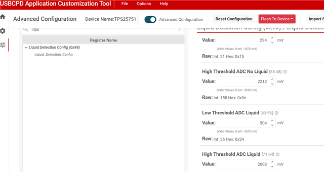
We are using TP 25751 USB PD controller and we have enabled the liquid detection with it through the USBC customization tool to generate the binary. We want to check the liquid detection with different configuration of the register 0x98 Liquid detection configuration register.

Can you help us to know the different values to write in the configuration register so we can increase the sensitivity for liquid detection like:
1. The controller can detect the moisture or liquid when the liquid amount or moisture content is high.
2. The controller can detect the lowest amount of moisture or liquid.

To test these scenarios what values would you suggest we can change in the configuration register? Please provide the reference and example values.
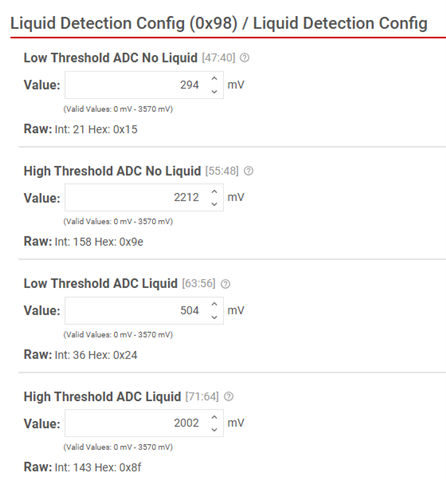
The by default values that we have read from the controller is:

001\0\001\0\002\021\158\36\143\170\6

  • Hi Runita, 

    Can you help us to know the different values to write in the configuration register so we can increase the sensitivity for liquid detection like:
    1. The controller can detect the moisture or liquid when the liquid amount or moisture content is high.
    2. The controller can detect the lowest amount of moisture or liquid.

    The high and low voltage threshold are configurable through these fields shown below. The field values are automatically inputted when the user selects 'Yes' to liquid detection on the GUI questionnaire page. These values are based on the TPS25751EVM hardware and may vary for custom designs. 

    The high measurement average is compared against the High Threshold ADC values to see if there are any shorts to ground. The low measurement average is compared against the Low Threshold ADC values to see if there any shorts to positive voltage. The high/low threshold value ranges from 3.3V to 0V for the register fields. Here are the details for each fields:

    • Low Threshold ADC No Liquid [47:40]
      • The low voltage threshold to exit the Liquid Detected state. The PD uses this value to compare against the low samples to determine if there are shorts to positive bias voltage pins. This field should be less than or equal to the Low Threshold ADC Liquid field, otherwise the PD will not be able to exit the Liquid Detected state.
    • High Threshold ADC No Liquid [55:48]
      • The high voltage threshold to exit the Liquid Detected state. The PD uses this value to compare against the high samples to determine if there are shorts to ground level pins (0V). This field should be greater than or equal to the High Threshold ADC Liquid field, otherwise the PD will not be able to exit the Liquid Detected state.
    • Low Threshold ADC Liquid [63:56]
      • The low voltage threshold to enter the Liquid Detected state. The PD uses this value to compare against the low samples to determine if there are shorts to positive bias voltage pins. This field should be greater than or equal to the Low Threshold ADC No Liquid field, otherwise the PD will not be able to enter the Liquid Detected state.
    • High Threshold ADC Liquid [71:64]
      • The high voltage threshold to enter the Liquid Detected state. The PD uses this value to compare against the high samples to determine if there are shorts to ground level pins (0V). This field should be less than or equal to the High Threshold ADC No Liquid field, otherwise the PD will not be able to enter the Liquid Detected state.

    The threshold values may vary based on your hardware design and how sensitive you want liquid detection to be on your board. For higher sensitivity, I recommend increasing the high thresholds and lowering the low thresholds. Make sure to double check the 'dry' state voltage on the SBU pins to make sure you don't accidentally set the threshold values outside the normal operation. For example, if the high threshold voltage is set to 3.0V but the analog voltage on the SBU line (in non-liquid condition) is actually 2.7V, this will lead to the PD detecting a false detection.

    Let us know if you have any further questions or concerns!

    Thanks and Regards,

    Raymond Lin

  • Hi Raymond,

    Can you also suggest the number of samples and sample time to increase the sensitivity? Also the calculations according to the register field descriptions.

  • Hi Runita, 

    By default the number of samples [39:32] is set for 4 total samples (2^2) with 1 second in between each measurement period. If you want to increase the measurement accuracy, you can increase the number of samples so that TPS25751 will take more measurement before averaging the values to determine if liquid is present or not. You can also change the delay settings between each sample period based on if liquid is present or not in the port. Here are more detailed descriptions for the number of sample and timing fields: 

    • Number of Samples [39:32]
      • The number of samples to take for both high and low measurements. This field value needs to be in terms of 2^n samples. For example, if this field is configured to be 0x3, the PD calculates this as 2^3 equals 8 samples and will take 8 high samples (when SBU lines are pulled high) and 8 low samples (when SBU lines are pulled low) during the sampling intervals.
    • Sleep Time in Seconds No Liquid [15:0]
      • The sleep timer/delay between each intervals of sampling in time units of seconds when there is no liquid/short detected on the USB Type-C connector. During this timer/delay VBUS and CC are active and the PD is in normal operation.
    • Sleep Time in Seconds Liquid [31:16]
      • The sleep timer/delay between each intervals of sampling in time units of seconds when liquid/short is detected on the USB Type-C connector. During this timer/delay VBUS and CC are disabled (if Enable Corrosion Mitigation 81b is enabled) and the PD is in Liquid Detected state.

    Let us know if you have any further questions or concerns! 

    Thanks and Regards,

    Raymond Lin

  • Hi Raymond, 

    After changing the register values as following, the device is not getting out of the liquid detection state, the register bit "Liquid Detection State" is not getting cleared.

    #define SLEEP_TIME_NO_LIQUID 0x1

    #define SLEEP_TIME_LIQUID 0x1

    #define SAMPLE_COUNT 0x3

    #define LOW_ADC_NO_LIQUID 0x08

    #define LOW_ADC_LIQUID 0x15

    #define HIGH_ADC_NO_LIQUID 0xCF

    #define HIGH_ADC_LIQUID 0xC1

    #define SAMPLE_TIME_NO_LIQUID 0xa

    #define SAMPLE_TIME_LIQUID 0xa

    We have observed SBU lines also, they are as per the dry state ie; 3V. is it necessary to clear the bit after the detection? as per my understanding it should get cleared automatically. Please let me know what could cause the issue. other than the register bit not getting cleared there are no signs of liquid detection on the device.

    When we are using the default configurations for the Liquid detection configuration register, which is set by the USBPD C customization tool, the device is getting out of the liquid detection state. But after making the changes in the register to make it more sensitive it is not getting out of the liquid detected state.

    Following is the default register values set automatically by the GUI. With these values the liquid detection state is getting cleared.

    #define SLEEP_TIME_NO_LIQUID 0x1

    #define SLEEP_TIME_LIQUID 0x1

    #define SAMPLE_COUNT 0x2

    #define LOW_ADC_NO_LIQUID 0x15

    #define LOW_ADC_LIQUID 0x24

    #define HIGH_ADC_NO_LIQUID 0x9E

    #define HIGH_ADC_LIQUID 0x8F

    #define SAMPLE_TIME_NO_LIQUID 0xa

    #define SAMPLE_TIME_LIQUID 0xa

  • Hi Runita, 

    How are you simulating liquid detection on your setup? Are you able to get scope capture of the SBU lines whenever "liquid" is presented on the port? 

    We have observed SBU lines also, they are as per the dry state ie; 3V. is it necessary to clear the bit after the detection? as per my understanding it should get cleared automatically. Please let me know what could cause the issue. other than the register bit not getting cleared there are no signs of liquid detection on the device.

    Which bit are you referring to? In the interrupt events there is a liquid detection INT to indicate when the state of liquid detection has changed (dry->wet and wet->dry both applies).

    The voltage thresholds may be too sensitive and in the 'dry' state, the threshold to enter liquid detection may be either the same or higher than the dry threshold. 

    Thanks and Regards,

    Raymond Lin