This thread has been locked.

If you have a related question, please click the "Ask a related question" button in the top right corner. The newly created question will be automatically linked to this question.

LMR38025-Q1: Non-ground Reference for Buck Step Down v. Inverting Configuration.

Part Number: LMR38025-Q1
Other Parts Discussed in Thread: LMR38025

Tool/software:

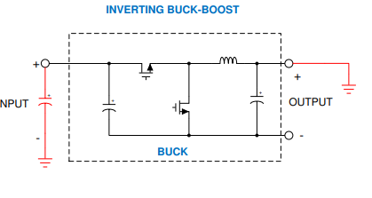
I'd like to use the LMR38025-Q1 so I can step down ±30V rails into ±20V rails for an analog device. While it seems like I'm still in the maximum specifications of the device at 80V I'm not too comfortable with the amount of power that I'd be dissipating across the device. I had previous issues with non-ground references in the past on TI Components so I thought I'd ask if I'd be able to reference the buck to -30V and then regulate such that I could get -20V out of it. 

In this configuration I'd have one device per rail and then be able to dissipate the power across both of the devices. 

Thanks!

  • Hi Mitchell,

    So we typically don't have a negative input to negative output buck converter, and don't recommend you do that with the LMR38025. What you can do is use a PWM controller to do so, as shown here: /cfs-file/__key/communityserver-discussions-components-files/196/The-Parallel-Universe-of-Negative-Input-Voltages.pdf

    But another way you could do is to use the step-down 30V rail, or 20V step-down output to generate the -20V, it should be 40V across the LMR38025, which is within limits. 

    Thanks,

    Richard

  • Hey Richard! Thanks so much for the information!

    Just to make sure I understand are you saying to use one buck to drop the voltage down from +30V to +20V then use an inverting configuration on the output of that to make -20V (I'm assuming by connecting ground to the output rail of the second one and then connecting the -20V to ground. Let me know if I'm misunderstanding what you're saying but I've seen inverting configuration that are similar to as I described and just wanted to make I understand.)

    Thanks!

  • Hey Richard! Just wanted to give more information to the previous comment that I left. This is the configuration that I was referencing as seen in "Working With Inverting Buck-Boost Converters" Application Note. 


    Also on a second note I'm assuming that we're still in specification assuming this device will be pushing ~1A of current correct. 

    Thanks!

    Edit #1: I did calculations based on the Application Note "Working With Inverting Buck-Boost Converters" and determined using Equation 5.1 found that at 1.64 MHz which was the recommended frequency by TI Power Designer that I should have a 22uH inductor on the output. Does this sound accurate to you - feels like a value more than I expected for a IBB but I don't have much experience with those designs. 

  • Hi Mitchell,

    Yes, that should be fine. I would recommend following the procedure outline with the app note.

    Thanks,

    Richard

  • Thanks Richard! You've been awesome!