Other Parts Discussed in Thread: TPS4H160-Q1
Tool/software:
Hello guys,
One of my customers is considering using TPS482H85-Q1 for their next products.
At this moment, they have the following questions.
Could you please give me your reply?
Q1.
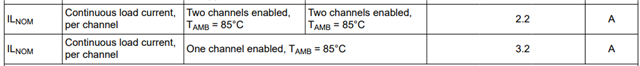
Can VOUT1 and 2 be tied together to increase output current twice?
Q2.
The device datasheet says on page1 "The TPS4H82H85-Q1 device is fully protected
dual channel smart high-side switch with two integrated 85mΩ NMOS power FETs
intended for 24V and 48V automotive supply systems".
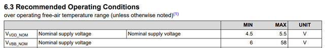
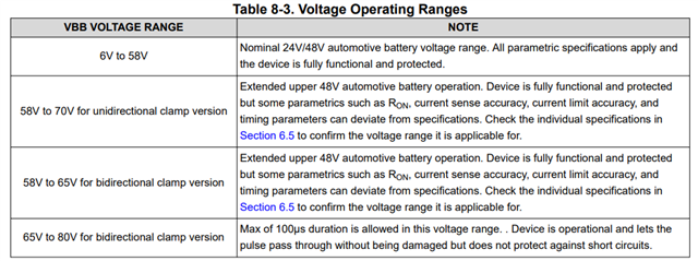
They want to use TPS482H85-Q1 with VBB=12V+/-10%.
Is there any performance change or concerning point?
Q3.
They are considering the following 3 devices.
TPS482H85A-Q1
TPS482H85B-Q1
TPS482H85C-Q1
Could you please give me these devices RTM timing?
Your reply would be much appreciated.
Best regards,
Kazuya.