A related question is a question created from another question. When the related question is created, it will be automatically linked to the original question.
If you have a related question, please click the "Ask a related question" button in the top right corner. The newly created question will be automatically linked to this question.
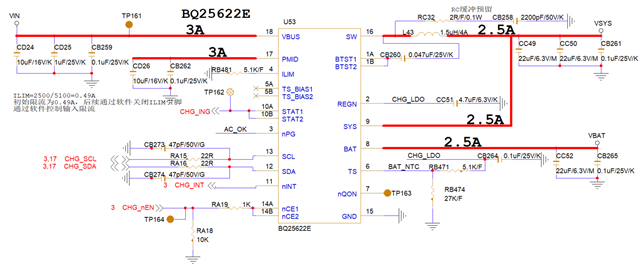
Please help check whether the schematic diagram and Layout are correct. If there are any parts that need to be modified, please explain in detail. Thank you!
-The capacitor at REGN is required to be a 10V or higher rated capacitor. Current schematic has a 6.3V rated capacitor.
-These pins are not required to be connected for operation, but if used /PG, STAT, and /INT pins require connection to a pullup rail through a resistor such as 10kohms. These pins are all open drain outputs so they only have the ability to pull low.
-What is reason for having 22ohms of resistance in series on SCL and SDA lines? This is not something I typically see when reviewing customer schematics.
Besides these comments the rest of the schematic appears okay. Required components are present.
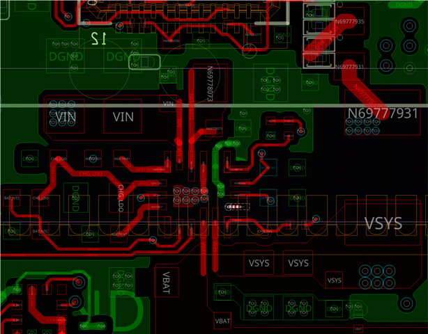
Layout:
I do not have any major concerns with the layout. Critical capacitors are placed near the IC as recommended in the Layout Guidelines section of the datasheet (Section 11.1).