Tool/software:
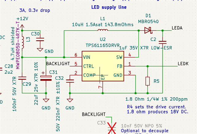
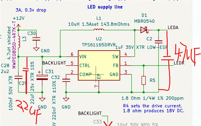
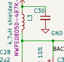
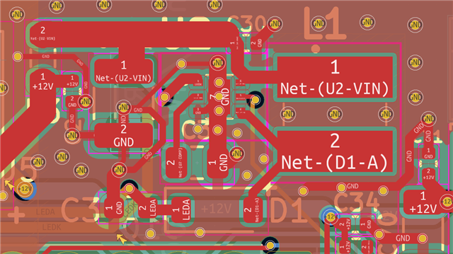
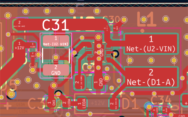
Our SDR design uses the TPS61165DRVR to drive the LED backlight on the LCD used to display the frequency spectrum, it is powered by the 13.8V input, we carefully followed the TI design guide and PCB layout.
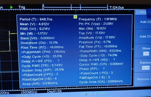
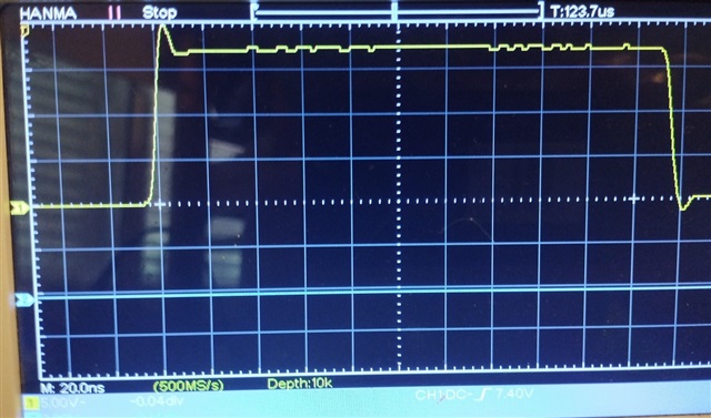
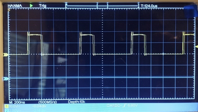
Problem: With the antenna disconnected, the 1.2 MHz signal from the 61165 is being detected at -95 dB, the haronics up to 7 MHz are also at -95 to -105 dB, which is causing interference with weak radio signals.
For most designs this wouldn't be a problem, but with an SDR radio design, it is.
We tried ferrite beads bu they don't really have much impedance until higher frequencies.
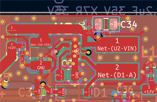
We have tracked the LEDA and LEDK lines side by side to reduce emissions, can be add 0.1uF decouplers to these lines to ground, or is there a better approach?
Our circuit is as per the datasheet.