


Tool/software:
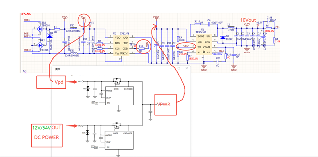
The rough schematic diagram is shown in the figure:
The simple principle is that the power from the POE and the power from the DC end are merged through an ideal diode to supply power to a DCDC buck converter for voltage reduction. The ideal diode is added to ensure seamless power switching.
The current issue is that when the DC12V line is powered and then the POE is connected, during the power switch, there is a power outage at the load end. When the POE is unplugged and switched to DC12V, the switch to DC12V power supply can be seamless. What is needed is a seamless power supply switch between POE and DC.
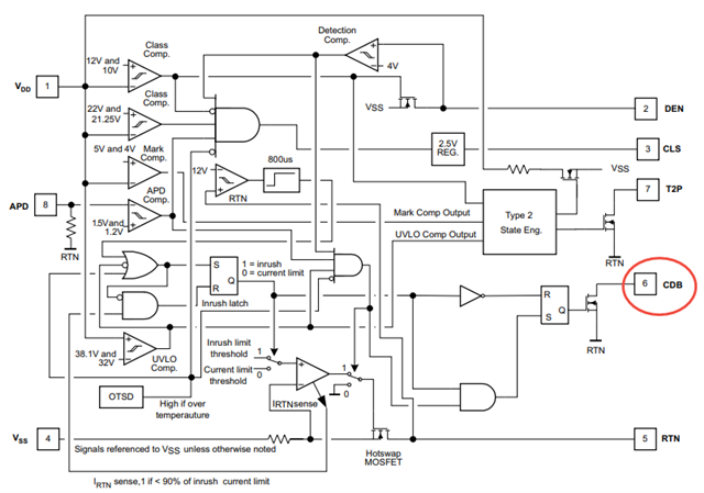
Here, when the POE was powered on, the EN pin of the DCDC chip was pulled low for about 18ms, causing the power supply to the back end to pause. I removed the resistor R33 and left the CDB pin of the TPS2378 floating. After connecting the DC12V, I connected the POE again but found no response. The POE end remained in the detection stage. According to the specification, CDB is in OD mode and should not be related to the POE detection. When only the POE is connected, the power supply works normally. Could you please help analyze the reason? How can we achieve seamless switching between POE and DC power?
Thank you very much!
大致的原理图如图所示:
简单的就是POE过来的点跟DC端过来的电经过理想二极管合并给一个DCDC buck供电降压,加理想二极管是为了无缝切换电源;
现在的问题就是:当DC12V线供电,然后POE上带,在电源切换的时候,负载端有掉电的情况,拔掉POE,切换DC12V可以无缝切换DC12V供电;需要的是POE跟DC之间在能无缝切换供电;
这边抓了一下波形是POE上电的时候DCDC芯片端的EN被拉低了18ms左右,导致暂停后端供电,我把电阻R33去掉,让TPS2378的CDB端悬空,在接上DC12V后,再接POE发现没反应,POE端一直处于检测阶段,从规格书上看CDB是OD模式,按理来说无关POE检测的事情,单独只接POE又能正常供电,求帮忙分析一下原因;怎么才能实现POE跟DC电源无缝切换电源;
非常谢谢~
