This thread has been locked.

If you have a related question, please click the "Ask a related question" button in the top right corner. The newly created question will be automatically linked to this question.

TPS2HCS08-Q1: Having trouble talking with Microcontroller via SPI

Part Number: TPS2HCS08-Q1

Tool/software:

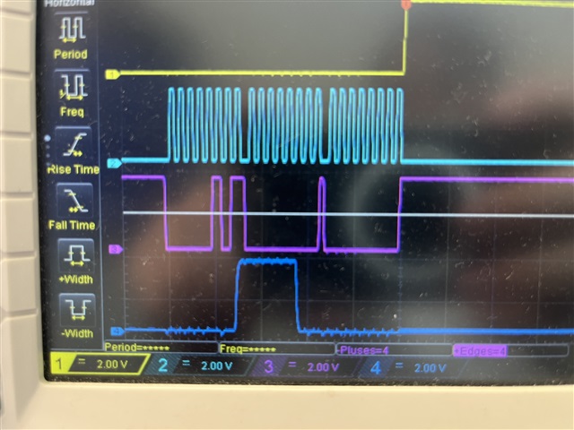
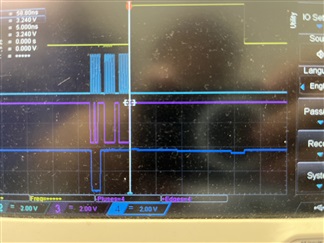
I have been trying to communicate with the Efuse via the onboard SPI pins using another Microcontroller as a master, and I get incorrect read data back from the Efuse registers. I have scoped the SPI commands, and they follow the specifications in the Efuse datasheet, but the data is coming back mainly as 0x80FF or 0x00F8, no matter which register I read from.

  • Jonathan,

    What phase/polarity settings are you using for your SPI peripheral? What is the clock frequency? If you could share a snippet of the host code (regardless of whatever MCU it is), this would potentially help us understand what is going on. 

    A good sort of sanity test would be to try to write 0x0003 to register address 0x07 (this should turn on both channels). For reference, standard header files can be found:

    https://www.ti.com/tool/download/HCS-HEADER-FILES

    Best Regards,
    Tim

  • I am using an ATSAME54P20 microcontroller that is on a SAME54 curiosity dev board. The phase is data sampling on a leading SCK edge and changed on a trailing SCK edge. The polarity is SCK is low when idle. The clock frequency is 1MHz
    This is a snippet of my code

    #include <stdio.h>
    #include <stdint.h>
    #include <stddef.h>                     // Defines NULL
    #include <stdbool.h>                    // Defines true
    #include <stdlib.h>                     // Defines EXIT_FAILURE
    #include <string.h>
    #include "definitions.h"                // SYS function prototypes
    #include "tps2hcs08.h"                  //Header for EFuse
    
    uint8_t txBuffer[3]= {0x04, 0x00, 0x00 };;
    uint8_t rxBuffer[3];
    size_t txSize = 3;
    size_t rxSize = 3;


    //Dummy write
    
    GPIO_PD11_Clear();
    RTC_Timer32Start();
    while(RTC_Timer32CounterGet() < 0x2);  //for t_ready time
    RTC_Timer32Stop();
    bool flag = SERCOM0_SPI_WriteRead(&txBuffer, txSize, &rxBuffer, rxSize);
    GPIO_PD11_Set();


    while(true){
    
    GPIO_PD11_Clear();
    SERCOM0_SPI_WriteRead(&txBuffer, txSize, &rxBuffer, rxSize);
    GPIO_PD11_Set();
    
    RTC_Timer32Start();
    while(RTC_Timer32CounterGet() < 0x2);
    RTC_Timer32Stop();
    
    }


    The GPIO is the CS pin.

    Here is also a photo of my osciliscope. The first wave is my CS pin, the second my SCK, the third my SDI, the fourth my SDO


    Thank you for helping me with this

  • Jonathan,

    While it's not the exact MCU, there are reference drivers/implementation for STM32H7 (as well as TI MCUs Slight smile) located here:

    https://www.ti.com/lit/pdf/slvaft2

    SPI mode 1 (polarity 0, phase 1) is the correct setting.

    I think maybe what is happening though is that the register reads do not populate on the same transaction... meaning the payload for the the register that you request is populated into the register and available on the subsequent read request. We do this to allow for management of reading in SPI daisy change configurations where there are multiple HCS devices setup in series. Could you try reading register address 0x00 twice? The second transaction, for the payload, you should be getting the device ID:

    If needed, I can capture a logic trace later today if you are still not able to get it to work. 

    Best Regards,
    Tim

  • I changed the phase and now the Efuse sends the correct data out for the reads, thank you