This thread has been locked.

If you have a related question, please click the "Ask a related question" button in the top right corner. The newly created question will be automatically linked to this question.

TPS3808E-Q1: Delay circuit with override

Part Number: TPS3808E-Q1
Other Parts Discussed in Thread: TPS38

Tool/software:

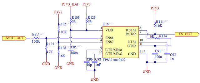
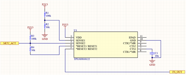
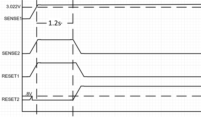
I have an application where an MCU will control an output pin that drives a relay (via a high side load switch). But if the MCU does not boot up I need the output pin to turn on after a set amount of time (1-2s), ideally adjustable.

I need an IC or circuit that will do the following:
Turn the output on immediately when there is a signal on the input.
If no input is present then turn on the output after a defined amount of time.

I was thinking I could utilise a reset or watchdog IC or maybe even a push button IC like the TPS3808E-Q1 or similar and take advantage of the active low reset pin, but I having a hard time working out the logic of this.

Any ideas? Thanks in advanced!

  • Hi Terry,

    If you could provide a few more details on your application it would help us work out a solution.

    What state will the output pin on the MCU be during power up? The initial state of the MCU output pin might cause problems with the delay circuit

    Do you need an open drain or push-pull configuration on the output?

    Does the output need to be active high or active low?

    -Henry

  • Hi Henry, 

    In my application my MCU needs to hold the high side switch off until the software has initialised, this is so other devices on the CAN bus network don't turn on until this device has turned on.

    I think I have an idea on how I can do this, but I have either over complicated it or it will not work at all...

    The TPS37A010122 has channel 1 assert reset low for over voltage, channel 2 asserts reset low for under voltage.

    https://www.ti.com/lit/ds/symlink/tps37-q1.pdf

    I have it configured as follows:

    P3V3_BAT is my permanent power source for the MCU backup domain.
    P3V3 is my switched source powered the MCU core and GPIOs.
    When P3V3 rises above ~3.3V for at least ~12.8ms FS_OUT will stay low for ~1.2s, after which FS_OUT will go high.
    When MCU_ACT rises above ~2.5V for at least ~128uS RSTn1 will pull down CTS2 which will discharge the capacitor and reset2 will be pulled up out of reset, therefore FS_OUT will go high. 

    Timings are set arbitrarily at the moment, values just placed for now and can be tweaked.

    Will this work as I intend it to?

    My only concern is that the datasheet doesn't mention that you can pull down the CTS pins, so the behaviour is potentially unknown, however you can pull down the CTR pins albeit the internal resistor is 10x higher on the CTR pins.

    The MCU override feature isn't a critical feature, the most important part is the delayed backup, so I may or may not put the 0R in between the RST1 and CTS2 pin, in case that doesn't work. 

  • Hi Terry,

    Thanks for the detailed information. Is the MCU_ACT signal held in high-Z mode before it is fully booted? If so, I think that you may be able to get away with a simpler configuration using a device like the TPS38 with active low overvoltage monitoring on both channels (TPS38J variants). Please see the simplified schematic below for reference

    On power up, once P3V3 stabilizes at 3.3V, RESET1 will go low after the time configured by CTS1. Assuming that MCU_ACT is in high-Z, this causes the voltage at SENSE2 to go below the threshold and RESET2 will go high. 

    When the MCU successfully boots it will have control over the voltage at SENSE2, allowing you to control the relay directly from the MCU.

    -Henry

  • Here is a timing diagram showing the operation when the MCU does not boot up in time: