Tool/software:
Hello Mike.
Vin:400 - 950vdc. Vout: 13.7, Iout: 0-75A. Cout: 12mF ( 2.5 times value suggested in excel tool ).
Transformer 1:
Turns ratio (Np:Ns) - primary to one half secondary ratio is 19:1
Center tapped secondary winding.
Leakage inductance: 12.6uH
Magnetizing inductance: 4mH +-10%
External inductor Lout : 2.2uH
Operating frequency primary MOSFETs: 95khz.
Transformer 2:
Turns ratio (Np:Ns) - primary to one half secondary ratio is 19:1
Center tapped secondary winding.
Leakage inductance: 19uH
Magnetizing inductance: 3.5mH +-10%
External inductor Lout : 2.5uH
Operating frequency primary MOSFETs: 125khz.
Problem statement:
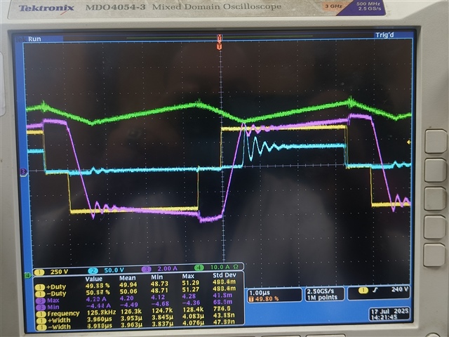
using transformer 1 , at 400Vdc, it's able to deliver 75A Maintaining Vout of 13.7V. But with transformer 2, the issue at hand is ( @25C ambient ) , at 65A above, vout is dropping from 13.7. last measured value is 12.3 @68A. As per manual calculation, max duty cycle at 400vdc is 0.71. As per excel max duty cycle is 0.66. but when I look at transformer primary voltage waveform ( @ 125khz, period : 8us, positive side , ON time waveform itself was going to 3.3us @65A itself which looks to me almost 83% duty cycle. Attaching waveform. Yellow colour waveform is transformer primary voltage.
Is the cycle by cycle of controller ( ucc28951) limiting the current and terminating switching cycle or turns ratio should be increased ? Presently current sense resistor at CT secondary is 39ohms. Planning to increase it to 30ohms to see if cycle by cycle current limit is an issue or not. What else could be done here ?? Please explain