This thread has been locked.

If you have a related question, please click the "Ask a related question" button in the top right corner. The newly created question will be automatically linked to this question.

TPS6593-Q1: LDO1 output for SD card interface

Part Number: TPS6593-Q1

Tool/software:

Hi Experts,

Customer did not implement power switch and the reset logic for supporting UHS-I SD card.

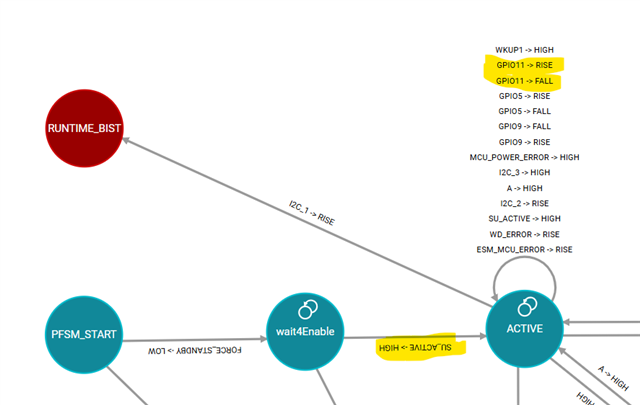
So customer cannot provide a low to high to the GPIO11 to enable SD card supply.

In case customer does no use UHS-I speed and the POWER switch to control the SD card supply and the power switch EN logic is not implemented, is there a recommendation to connect GPIO11.

Currently the GPIO11 is left open and the LDO output is not available.

Regards,

Sreenivasa

  • Hi Sreenivasa,

    Can you please provide the full long part number (OPN) that the customer is using? We need this to understand the NVM configuration of the device, so we can make an accurate recommendation. 

    Regards,

    Katie

  • Hello Katie

    Thank you for the reply.

    Please refer below.

    PTPS65931211RWERQ1

    Regards,

    Sreenivasa

  • Hello Kallikuppa,

    In case customer does no use UHS-I speed and the POWER switch to control the SD card supply and the power switch EN logic is not implemented, is there a recommendation to connect GPIO11.

    In short, the recommendation is to ground GPIO11, now GPIO11 is tied to enabling LDO1.

    Setting on the TPS65931211 for GPIO11:

    As for the output settings for LDO1:

    BR,

    Nicholas McNamara

  • Hello Nicholas McNamara

    Thank you for the inputs.

    I may have not had the question right or complete - please see below:

    n case customer does no use UHS-I speed and the POWER switch to control the SD card supply and the power switch EN logic is not implemented, is there a recommendation to connect GPIO11 for the LDO1 to output 3.3V 

    Regards,

    Sreenivasa

  • Hello Kallikuppa,

    For the customer, depending on what software they're using they can just connect it to one of the GPIOs on the AM62A and toggle it that way.

    As for enabling LDO1, it can be turn on via software writes. Now it should be mentioned that with the 5V0 input of VCCA the following should be adhered to since LDO1 is by default a load switch for 3V3. If it does not see the 3V3 on the input when enabled it will flag and interrupt and attempt to restart. This configuration for bypass vs linear regulator mode can be changed via softwarewrites

    The question on the recommendation for the GPIO11, please have this answered by the Sitara team as their recommendation as per their software package.

    BR,

    Nicholas McNamara

  • Hello Nicholas McNamara

    Thank you.

    Customer is using SD card for boot.

    Based on the above inputs, i understand there is no way to output 3.3V on LDO1 without the GPIO11 input transitioning from 0-1.

    Is my understanding correct?

    Regards,

    Sreenivasa

  • Hello Kallikuppa,

    Not quite correct, but from a hardware standpoint, your statement is true.

    Now LDO1 can transition from 0-1 using an software (I2C) writes to change the state. There are several software writes involved with this method, and some question regarding their implementation needs to be answers and accounted for.

    For example what is the input voltage on the PMIC (VCCA pin).

    BR,

    Nicholas McNamara

  • Hello Nicholas McNamara

    Thank you.

    When i am using the SD card for boot and if the processor IOs connected to SD card interface are not enabled, the processor will not boot and hence there will be no software running.

    VCCA connects to VCC_3V3_MAIN (same as PMIC buck input).

    Regards,

    Sreenivasa

  • Kallikuppa,

    Thank you for the context, this actually helps explain the problem and why you need all of the other details.

    So unfortunately, it's not until the PORz (PMIC's nRSTOUT pin) goes high will the PMIC react to the anything on GPIO11 (SD_CARD enable, LDO1 on PMIC) as seen below on the diagram.

    If the customer had to make a "blue wire" connect for GPIO11, it have to be a signal after the PORz goes high on the system. So it can not be tied to the VCC_3V3_MAIN as the GPIO11 reacts to a rise condition on the pin.

    Okay so no special software considerations if there was software to turn on LDO1, but the issue now is that there needs to be a hardware signal to GPIO11 after the PORz goes high. Suggestion of a domain that goes high after the PORz is asserted.

    BR,

    Nicholas McNamara

  • Hello Nicholas McNamara

    Thank you.

    If i can summarize the inputs, the only wany to enable the LDO1 is for the input to GPIO11 go from low to high after the nRSTOUT pin goes high.

    I suspect there is no concern in terms of input slew in case any of the switched 3.3V supply is connected.

    Ex VCC_3V3_SYS load switch output on the AM62A controlled by the SOC GPIO 

    Regards,

    Sreenivasa

  • Hello Kallikuppa,

    If i can summarize the inputs, the only wany to enable the LDO1 is for the input to GPIO11 go from low to high after the nRSTOUT pin goes high.

    That is correct.

    I suspect there is no concern in terms of input slew in case any of the switched 3.3V supply is connected.

    There are limitations on the pins as from the line items above, just for awareness, but rarely would this ever get violated. These line items imply that the VIO_IN should NOT ramp up before the VCCA/PVIN pins, other than that no concerns from the PMIC side.

    BR,

    Nicholas McNamara

  • Hello Nicholas McNamara

    Thank you.

    Regards,

    Sreenivasa