This thread has been locked.

If you have a related question, please click the "Ask a related question" button in the top right corner. The newly created question will be automatically linked to this question.

TPS61288: Circuit doesn't work on 5V input and 12V output

Part Number: TPS61288

Tool/software:

Hi,

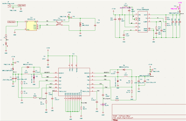
I am sharing the circuit for the TPS61288RQQR. When I connect the LED-strip load to the 12 V output, the voltage drops to 9 V. Please review the schematic below and let me know how to fix this issue. The PCB is already built, so I’m looking for the smallest possible modification that will resolve the problem.
Requirements:
• 12 V output for LED strips
• 1 A maximum continuous current

  • Hi,

    Please let me know the load current when operating. Also may I know how may cells LED are used?

    As I know for LED loads, the output voltage is decided by LED itself, and the DC-DC converter is usually used to control the output current as shown below, FB is used to sense output current instead of output voltage, I am not sure if this is your application, but anyway attach this figure for your reference.

    Regards,

    Nathan

  • Hi Nathan, 

    I appreciate your response. I’m using the TPS61288, but I’m not sensing any load current. The purpose of the TPS61288 in my design is to supply power to LED circuits. The circuit drives 4 LED channels, each drawing 18 mA. Would you mind reviewing the circuit I shared at the beginning? Thank you!

  • Hi Fahad,

    Thanks for the information. The schematic looks ok, the only one which can be improved more would be the COMP capacitor, C81 can be reduced to ~5nF.

    But I don't think this would be a cause of voltage drop, how about the input current when the output voltage drops? Can you share some waveforms of VIN SW, VOUT node for checking?

    Also I am not sure very sure, but maybe connect a resistor series with the LED channel could be helpful.

    Regards,

    Nathan