Tool/software:
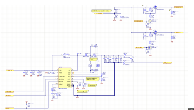
We use the “TPS923655DMTR“ in our LED Driver. Our boost regulator schematic is almost similar to the “TPS92365xEVM 65-V, 2-A/4-A Boost/Buck-Boost LEDriver Evaluation Module “
And it works fine. We passed all electrical tests with many special supply behaviours (e.g. transients / bursts / unstable), our emc tests und temperature tests.
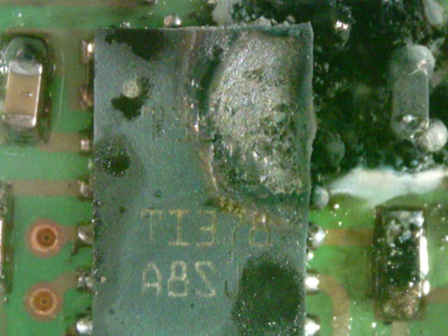
But once the TPS923655DMTR burned off by following conditions:
- 24V (DC supply Imax 10A)
- low resistance supply wires (2,5 mm2 / length 1m)
- the LED driver immediately starts after power ON
- I_led = 1A
- U_led = 28V
Unfortunately, I connected the supply wires (laboratory plugs) too slow, so I got some voltage bouncing. I heard sounds like ringing / cracking noise.The boost regular was not stable and the TPS923655DMTR burned off. Maybe my DC supply and the TPS923655DMTR were swinging in phase (positive feedback). It took only approx. 1-3 seconds. Then the LED driver was dead.
Has anybody comparable problems?
Now, we are starting our mass production of our LED lights, so we are a bit worried about this behaviour. We are thinking about some SW workarounds, e.g. to wait for a stable supply voltage. Our microcontroller can measure the supply voltage. After the supply voltage is good, we could start the boost regulator softly. But we still don’t know if this workaround helps in every situation. We can switch off the LED String, we can measure the supply and LED voltage.