A related question is a question created from another question. When the related question is created, it will be automatically linked to the original question.
If you have a related question, please click the "Ask a related question" button in the top right corner. The newly created question will be automatically linked to this question.
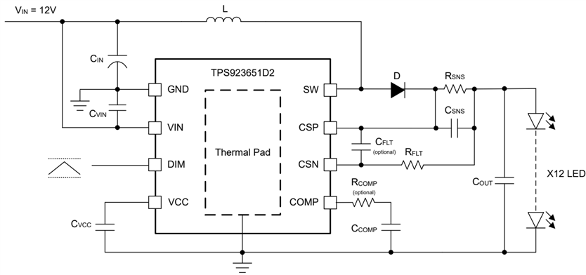
[FAQ] TPS923651: What is the LED current that TPS923651 can support with Boost configuration?
For TPS923651/0, the maximum LED current that it can support is not the switching FET cycle-by-cycle current limit which is different from TPS922051 which is Buck LED driver.
1. Necessary Parameters of the Power Stage
The following parameters are needed to calculate the power stage:
Input voltage: VIN
Output voltage range (Total LED string forward voltage): VOUT
LED current: IOUT
Switching frequency: FSW
Inductance: L
2. Calculate the inductor peak current
The first step to calculate the inductor peak current is to determine the duty cycle D.
The efficiency is added to the duty cycle calculation, because the converter has to deliver also the energy dissipated. This calculation gives a more realistic duty cycle than just the equation without the efficiency factor.
The next step is to calculate the inductor ripple current.
The maximum switch current in the system is calculated:
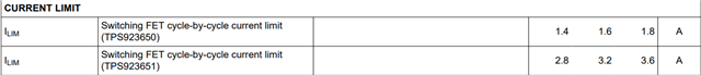
This is the peak current that the inductor, the integrated switch and the external diode has to withstand. For TPS923651/ TPS923650, you'll find the switching FET cycle-by-cycle current limit as shown in datasheet.
It means that for TPS923651, the maximum switch current should be lower than the minimum switching FET current limit (2.8A) with some margin. And for TPS923650, the maximum switch current should be lower than the minimum switching FET current limit (1.4A) with some margin.
For example, suppose VIN=12V, VOUT=24V, IOUT=1A, FSW=400kHz, L=33uH, Eff=90%, ISW(max)=2.47A. (<2.8A) Thus, there is no problem to support this application.