This thread has been locked.

If you have a related question, please click the "Ask a related question" button in the top right corner. The newly created question will be automatically linked to this question.

LM76002-Q1: LM76002QRNPTQ1 output stuck around 2.5V–3V with unstable oscillation instead of regulated 5V

Part Number: LM76002-Q1
Other Parts Discussed in Thread: LM76002

Tool/software:

Hello TI Technical Team,

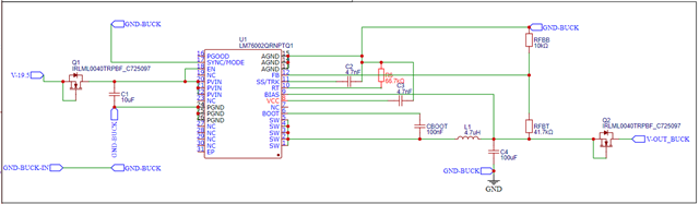
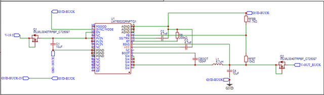
I am using the LM76002QRNPTQ1 IC to step down from 19.5V to 5V, but I am facing an issue:
The output voltage only reaches around 2.5V to 3V, even when no load or light load is connected.
I measured the FB pin voltage and found it to be only 0.3V.


Gear️ My current circuit configuration:

  • VIN: 19.5V

  • Target VOUT: 5.0V

  • Feedback resistor divider:

    • RFBT = 40.52kΩ (Part: TNPW040239K7BEED)

    • RFBB = 9.99kΩ (Part: MCS0402MD1002BE500)

  • Inductor: 4.7µH, DCR low, rated >2.5A

    • (Part: XAL7070-472MEC)

  • Output capacitor: 1 × 10µF ceramic

    • (Part: GRM188R6YA106MA73J)

  • SS/TRK: Floating (not connected)

  • BIAS: Connected to VOUT

  • EN: Pulled up to VIN


Mag Observations and symptoms:

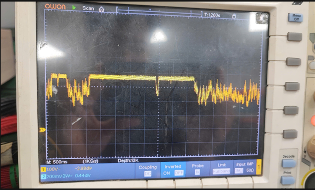
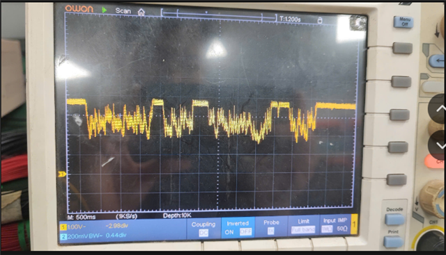
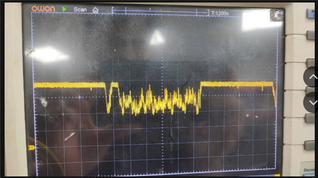
  • Output voltage never reaches 5V — it stays around 2.5V to 3V and constantly fluctuates/oscillates near that range

  • After removing RFBT and RFBB, resistance between FB and GND = ~30 MΩ, which suggests no internal short in the IC

  • Feedback voltage measured at FB pin is ~0.3V, far below the 1V target

  • Resistors are verified, soldering re-checked, and PCB cleaned with IPA, but the issue persists


Question I would appreciate your help on:

  1. Is there any reason the IC would limit VOUT or fail to reach regulation in this condition?

  2. Could a hidden layout or IC fault cause this behavior?

  3. Are there any protection modes that may explain this unstable low output?

Thank you very much for your support.

  • Hi Hieu,

    Can you flip the RFBT and RFBB resistors? RFBT should be 40.2k, RFBB should be 10k.

    Also, RT resistor should be in between 134K (300kHz) and 17.57K (2200kHz). Would recommend replacing RT so frequency is in between 500kHz and 1MHz, and increase output capacitance in between 100uF and 66uF. You can see table 2 in datasheet as reference. 

    Let me know if that works.

    Thanks,

    Richard 

  • Dear TI Technical Support Team,

    Thank you for your previous assistance regarding the LM76002QRNPTQ1 buck regulator.

    I have carefully applied all the recommendations provided, including:

    • Adjusting the feedback resistor divider:
      RFBT = 41.7kΩ, RFBB = 10kΩ → Target VOUT = 5V

    • Setting the RT resistor to ~66kΩ → switching frequency ~750kHz

    • Increasing output capacitance to:
      1 × 100µF (GRM21BR60J107ME15K) and 1 × 10µF (GRM188R6YA106MA73J)

    • Using XAL7070-472MEC (4.7µH) inductor rated >2.5A

    • EN pin tied to VIN, BIAS tied to VIN

    • 0.1µF capacitor properly installed between BOOT and SW

    • SS/TRK connected to GND via 4.7nF capacitor


    Mag However, the issue still persists:

    Despite the changes above, the regulator still fails to achieve 5V output.

    Observed behavior:

    • VOUT only reaches ~3V with no load, and drops to ~2V under load

    • FB pin voltage remains around 0.4V (instead of expected 0.8–1V)

    • No overheating or excessive current draw

    • Resistor values and soldering have been checked multiple times

    • IC has been replaced once, but the issue remains identical


    Wrench Additional notes:

    • Layout is carefully routed: FB, RT, SS traces are short and properly grounded

    • Input voltage is stable at 19.5V


    Point right I would really appreciate your support on the following:

    • Are there any other conditions that could prevent the IC from initiating switching?

    • Could there be an internal fault or soft-start issue still blocking proper operation?

    • Are there known errata or layout sensitivities that could cause this?

    I am happy to provide photos, layout snapshots, or oscilloscope waveforms if needed.

    Thank you very much for your continued support.

    ...

  • Dưới đây là bản dịch sang tiếng Anh:


    I have tested with 30uF, and it seems the power supply is more stable, but the voltage still doesn't appear clean and steady. Could you please guide me on how to fix this issue?


  • Hi Hieu,

    A few comments-

    1) BIAS should be connected to VOUT, or ground if not used. 

    2) Can you leave SS floating? 

    3) Do you have an existing LM76002 EVM? Who's your local FAE contact? Can they ship you an EVM? 

    4) After the startup, can you give me a scope shot of VIN, VOUT, SW, SS during startup and steady-state? Please allow enough time for all waveforms to reach a steady-state. 

    ///

    Are there any other conditions that could prevent the IC from initiating switching?

    - Could be current limit, 

    Could there be an internal fault or soft-start issue still blocking proper operation?

    - If left floating, we should see a 6.3ms start up. 

    Are there known errata or layout sensitivities that could cause this?

    - Can you take a picture of your hardware setup, and also provide the schematic + layout files? If you have it in Altium, or cadence allegro files, the better. 

    ////

    Thanks,

    Richard

  • BIAS Pin Connection:
    I have connected the BIAS pin to VOUT as recommended in the datasheet.

    SS (Soft-Start) Pin:
    I have tried both configurations: leaving it floating and connecting a 22nF capacitor to GND. However, the issue where the IC fails to start still occurs in both cases.

    EVM (Evaluation Module):
    Currently, I do not have an EVM board for the LM76002 to perform a reference test. If possible, I would appreciate support from a local FAE in Vietnam to quickly obtain an EVM for testing.

    Other Issues:
    I have considered the possibility of current limit triggering, but I am using a 4.7µH inductor and a 5V/2A load (with no active current limit on the output), so the likelihood of an OCP event is very low.

    I will continue to capture startup waveforms of the following signals: VIN, VOUT, SW, and SS, and send them in the next email to provide more information for your evaluation.

    In addition, I am preparing to send the full schematic and photos of the actual hardware to further assist in analyzing the root cause of the IC not switching.

    — Attached below are the schematic and PCB layout files of the entire circuit.

  • Hi Hieu,

    I'm working internally to see who can locally support you. 

    In this case, let's isolate the converter. Can you disconnect the LM76002 from the external circuits and see if it is able to start up at no load and full load?

    Thanks,

    Richard