This thread has been locked.

If you have a related question, please click the "Ask a related question" button in the top right corner. The newly created question will be automatically linked to this question.

BQ76952: BQ76952: I can't communicate with bq76952

Part Number: BQ76952

Tool/software:

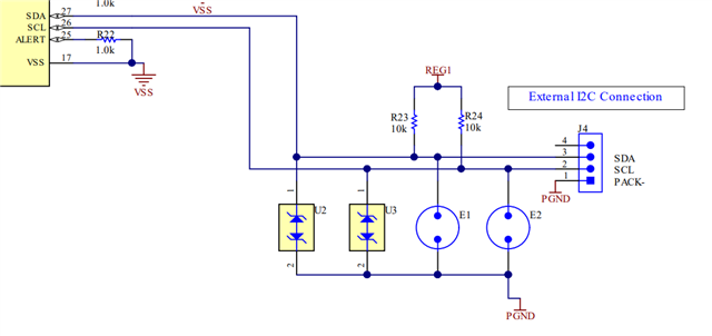
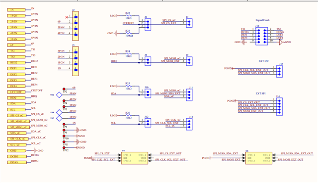
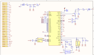
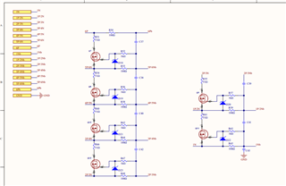
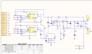
I created a pcb with the bq76952 similar to the evaluation board (bq76952evm) but designed for 6 cells. The circuit is shown in the figure below, as well as the conditioning circuit for reading the cell voltage.

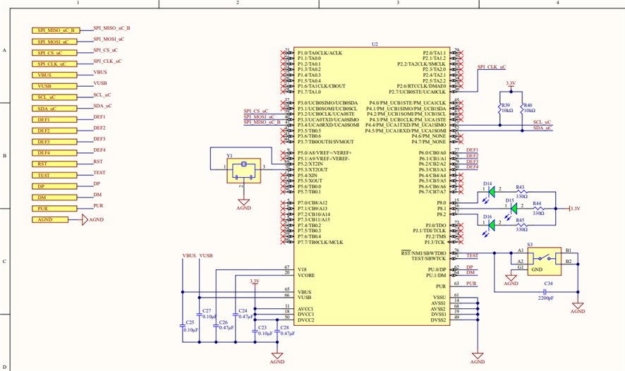
On the microcontroller side (MSP430FR5529), communication is being carried out correctly as we have tried to communicate with the bq76952 on the bq76952EVM board with our microcontroller and succeeded.
However, we are unable to communicate with the bq76952 on our board, we believe that it is in shutdown mode and does not exit it. Although we have already done the bq76952 initialization process, which follows these steps

-Power on the BAT pin
-Press the wake-up button connected to the ts2 pin
-Attempt to communicate via I2C with the BQ76952 board (100 KHz in I2C)

The BQ76952 does not respond, giving a communication NACK right from the Adress.

NOTE:
- We measured the reg18 pin and it shows 1.8v on its output.
- The bat pin gets 17v since we're only using 6 cells;
- On the CP1 pin we get 28V;
- On REG1 and REG2 0v;
- REGIN O.13V;

That said, the question is where are we going wrong that the bq76952 isn't communicating with the microcontroller?

  • Hello Rafael,

    The Reg18 pin displaying 1.8V on its output would suggest the BQ76952 is awake and operating so being in shutdown mode should not be the issue.

    I noticed on your schematic that you do not have any pull-up resistors on the SDL and SDA pins. Our device does not have any internal pull-up resistors, so it is required to add external pull-up resistors for i2c to work properly. This could be one of the reasons communications is failing. Try adding pull-up resistors to those pins and let me know if anything has changed.

    This image can be found in the datasheet, but I have pasted it below as well for a guide:

    Regards,
    Rohin Nair

  • Hello, good morning, and thank you in advance for your response. I didn’t include all the schematics of the circuit, but yes, we had already added the Pull-Up resistors previously, as can be seen in the following figure. 

    We closely followed the architecture already implemented by Texas Instruments in the BQ76952-EVM, only adapting it for 6 cells

  • Hello Rafael,

    Nothing stands out to me as an issue after looking at your schematic. Can you measure the Voltage of the TS2 pin and LD pin and let me know what the values are for that? Your device may be entering a soft shutdown state which could interrupt communication.

    Regards,
    Rohin Nair