This thread has been locked.

If you have a related question, please click the "Ask a related question" button in the top right corner. The newly created question will be automatically linked to this question.

UCC21750-Q1: question on RDY behavior

Part Number: UCC21750-Q1
Other Parts Discussed in Thread: UCC21750

Tool/software:

Hi team, 

We got a question from customer as below. 

Below is start up waveform on UCC21750. CH1=input PWM, CH2=RDY PIN, CH3=RESET PIN, CH4=VCC. There have external pull up at RDY PIN. I want to know why RDY will go high when RESET have a short low pulse, VCC just go to >2.85V. 

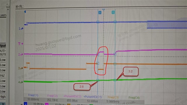
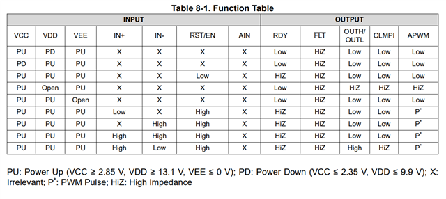
This is unknown condition which is not show in below table. In this case, VCC should be PU, VDD is PD, RESET is low, what is correct behavior for RDY PIN state? 

Thanks!

Ethan Wen

  • Hi Ethan,

    Thanks for reaching out to us, Can you please share the setup ( how different pins are connected to supply in customer system)?

    Another key thing to note, based on the waveforms, EN/RST ~5V is higher than VCC (~2.8V) during powerup, which violates the absmax conditions and also hence not a valid start up condition. Can we please recommend customers to keep EN/RST pin < VCC during power up? 

    Thanks

    Sasi

  • Hi Sasi, 

    EN/RST is connected with MCU. This is powered when MCU power up. VCC and RDY pull up source come from same 5V rail. VDD start up along with VCC. 

    Already suggested customer to keep EN/RST pin < VCC during power up. 

    Do you know the correct behavior for RDY pin(in red box) when RDY is low, VCC is PU, VDD is PD? 

    Thanks!

    Ethan Wen

  • Hi Ethan,

    RDY pin will be high for VCC>UVLO and VDD> UVLO, for all other conditions RDY should be low.

    However, when EN > VCC, it violates the device functional behavior as it goes into non-functional mode. So it shouldn't be exercised and the RDY behavior is unexpected. 

    it will be great if you can share customer schematic specific to gate driver, for us to understand it better.

    Thanks

    Sasi