This thread has been locked.

If you have a related question, please click the "Ask a related question" button in the top right corner. The newly created question will be automatically linked to this question.

LP5817: Questions about the Shutdown/Standby mode.

Part Number: LP5817
Other Parts Discussed in Thread: HDC2010, LP5009, LP5811, LP5814, LP5562

Tool/software:

We are considering the LP5817 as driver for the RGB signal LED on an IoT sensor. This LED needs only to blink 1,2 or 3 times occasionally in one color. So nothing fancy. Still it makes sense to use a special driver for that, since controlling it from the MCU directly takes up too many IO lines. The important requirement is: no energy waste while doing nothing. The  LP5817 has two low power options. "STANDBY"  and "SHUTDOWN". The former consumes 22uA continuously, which is way too much for a battery powered device. We accept ~1uA max for inoperative devices. This leaves us with the "SHUTDOWN" mode. According to the datasheet there are two ways to enter this mode (page 15-16 of document SNVSCQ2 – MARCH 2025):

Figure 7-5 shows the method 1:

  • Enter shutdown, send Shutdown_command by writing 0x33 to register 0xD though I2C communication.
  • Exit shutdown, toggle SDA 8 times to generate 8 falling edges while keeping SCL as high. The supported maximum toggle frequency for SDA is 100kHz.

So here you manually set Shutdown in action by writing to a register which is fine, but can only wake it by sending and I²C illegal control sequence. (In fact 8 start-stops, which are illegal under the I²C specification Rev7.0, paragraph 3.1.10 Note 5). Other devices on the bus may enter an inconsistent state. And:

Figure 7-6 shows the method 2:

  • Enter shutdown, pull down SCL for 100ms while keeping SDA as high.
  • Exit shutdown, pull up SCL to generate one rising edge regardless of SDA state.

Pulling down SCL before SDA is not mentioned in the I²C specification, which may lead to inconsistencies as well, and some devices are known to interpret this as "stalled bus state" due to long time that SCL is down and completely reset their internals. Furthermore, if i take the text literally, the Shutdown state would only last 100ms since after that we pull up SCL again. I assume this is not what is intended. Should this be read as "Pull up SXCL after the first change on SDA"?

Now my questions are:

  • Have i correctly understood that the only way to activate the shutdown mode is by one of these illegal I²C commands?
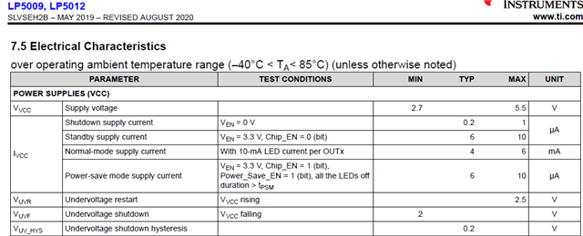
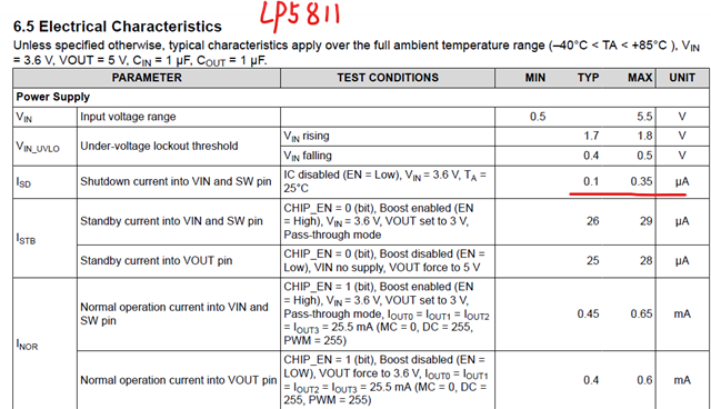
  • Is there an alternative LED driver chip that has a STANDBY current <1uA or a regular sleep mechanism like TI's HDC2010? 
  • Was my interpretation on method 2 (in red) correct?

Thank you very much for any guidance.

Ruud 

  • Hi Ruud,

    Yes, your understanding of the entering and exiting shutdown mode methods are correct. So in your application, is it not possible to generate the specified waveforms on the SCL/SDA?

    If not, recommend to take a look at the LP5009, which support shutdown mode with 1uA current and power save mode (when all channels are off) with 6 uA current.

    If you think the LP5009 has more numbers of channels than you required, recommend to take a look at the LP5811, 4-channel I2C RGBW led driver (which boost circuit can be by passed), which supports less than 1uA quiescent current with EN pulled low.

    best regards,

    Felix

  • Hi Felix,

    Thank you very much for taking the time to give such an extensive answer, i really appreciate it.

    We could generate the required sequences in software to bring the driver to shutdown, but we rather would not, since we do not know on beforehand how the other I²C devices would behave. Even if we test this for the current design, upgrades later in time may behave differently. So, although i have great respect for the engineers that came up with this igneous solution, we would prefer it if IT adheres to the I²C protocol, as the majority of the chips from TI do.

    That said, you suggested two alternatives we might consider.

    • We considered the LP5811, which is a nice chip indeed, but shutdown there can only be achieved by an extra line (EN), which we do not have available. The standby current (26uA) is too high for our purposes. 
    • The LP5009 is an interesting solution we did not yet consider, indeed since it dropped out of our filter because of having more channels. This chip also requires an extra line to go to shutdown mode, but the power save mode looks better here, with ~6uA. Formally, it exceeds our design requirement for an inactive chip so this has to be discussed.

    We also considered the LP5562, which has a standby current (when software enabled) of only ~2uA. This would be perfect, but it is a somewhat older chip, and TI advices to make use of the LP5814 instead, which is like the LP5817 regarding the shutdown procedure. But since the LP5562 is older and due to this advise we fear it may be EOL somewhere in the near future. 

    Thanks again and best regards, Ruud.

  • Hi Ruud,

    Really appreciate your so detailed comments.

    Based on that i also think the LP5562 is the best one at present.

    As for the EOL, I didn't hear and see any clue that would EOL this device. Though we recommend the LP5814/7 that because these are all latest released devices. But as you have found there were still several function gaps between the new devices and at present the LP5562 is still used by lots of customers.

    So, i don't think you need to have concern about the lifetime of LP5562.

    And i will deliver this information to our system engineer. And decide how to obtain the same level quiescent current through normal method (e.g. standard I2C command protocol) in a new device.

    Best regards,

    Felix

  • Hi Felix,

    This is great news. We will put the LP5562 on the short list for further evaluation.

    I also really appreciate it that you pass the information to your engineers. Regarding this, i like to add

    • It is completely clear that, when you like to bring the current down to 100nA, you need all clever tricks at your disposal. So this out-of-band messaging of the LP5817 on the I²C bus quickly comes to mind. However, energy consumption is about the sum of all contributions. Normally, on battery driven devices traffic on the I²C bus is low. So it is perfectly reasonable to let the chip wake up shortly from shutdown to standby at the start condition to compare the address ID on the bus. If it is not targeted, it returns back to shutdown mode. Even if the current consumption during that time is 10uA or more, it does not impact the overall power budget much.
    • Making use of illegal codes on the I²C bus has an other disadvantage except from the one mentioned earlier. When you make use of abstractions in the software and have separately developed, tested and approved libraries for communication like I²C, SPI CAN etc, there is no way you can (or even want to) add this behaviour. So that automatically rules out the chip for use. We are not there yet, but certainly striving for it. 

    That's it. Thanks again, and if we have further questions on the LP5562 i will open a separate thread.

    Ruud.

  • Hi Ruud,

    Thanks for your additional comments. I will pass the information to our engineers and let you know if there is any update.

    And also please let me know if you have any further questions on the LP5562.

    Best regards,

    Felix