This thread has been locked.

If you have a related question, please click the "Ask a related question" button in the top right corner. The newly created question will be automatically linked to this question.

TPS92692: Input to output delay - Startup and Normal operation

Part Number: TPS92692

Tool/software:

Hi Team,

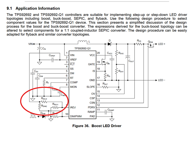
We are considering TPS92692 for one of our designs. The input is 9V-36V. The output current is expected to be around 10A at 50V.

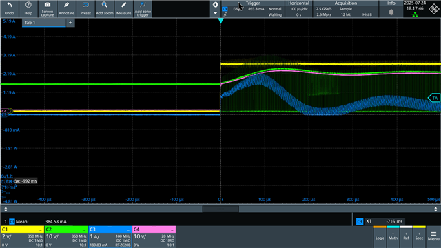
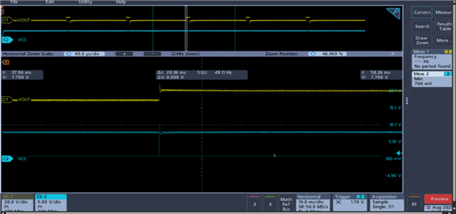
The PWM input is from 1Hz to 67Hz. The on-time for all of these is 1ms (fixed) and the off-time varies accordingly from 14ms to 999ms.

Ideally, we want the LEDs to turn on during high of PWM and turn off during low instantly. The DS gives a delay of 326ns which is acceptable.

We previously considered, TPS923655HMDMTR. But, 999ms low on PWM seems to disable the device. And there is a 5ms delay during start-up, which is not acceptable.

Is TPS92692 a suitable option for this application?

Thanks,

Jagan

  • Hi Jagan,

    What is the end application for this project?

    Our devices really aren't built to handle 500W... did you mean 1A?


    Are you willing to parallel multiple devices? How are you managing your thermals?

    Best,
    Daniel

  • Hi Daniel,

    The end application is robotics. We require this level of illumination to capture images in dark.

    As per this previous post [TPS92692: reference design of 24Vin, 30~50Vout/10A current? - Power management forum - Power management - TI E2E support forums], the device is capable. Are there any other limitations for this device? Our understanding is that, the limitations are imposed by the external components only. As long as we pick a capable FET, Inductor, etc, the design should work. Is our understanding correct?

    If the device will enter start-up every time, what will be the expected delay during start-up? Are there any ways to optimize this or does this have any work arounds?

    We are okay with paralleling multiple devices.

    If there are any alternate drivers for this, please let me know. We are also open to any other alternate approaches for this.

    Once we finalize the electrical design, we'll check thermal.

    Thanks,

    Jagan

  • Hi Jagan, 

    The device is capable in theory. It will be extremely hard to realize this design and we advise against it. As I mentioned, this device is not meant to handle 500W. If you choose to go that route you will encounter complications. 

    Additionally, your device at low-line voltage will pull over 50A, which is much greater than the current needed in the post you referenced. You will need a very stable power supply and very large capacitors at the input to insure the transient isn't too large and the compensation network can handle it

    As Tuan mentioned in the post you referenced, you will need to purchase gate drivers in addition to FETs that can handle the current you intend to output. 

    On a positive note, I have verified there is no delay whatsoever when PWMing at 1Hz with 1ms on time. Keep in mind, the EVM I used here is not compensated properly and therefore the oscillations can be mitigated. This was purely to show that it works with the lowest PWM frequency at the lowest duty cycle you referenced. 


    You can parallel multiple channels to achieve higher currents with better thermals. The TPS92682 is essentially the same part with a digital block and two phases.

    Best,
    Daniel

  • Hi Daniel,

    Thanks for measuring and confirming there's no delay.

    Would it be possible to design this using two drivers in parallel? If not, could you please provide a reasonable estimate of the maximum power a single driver can handle, assuming it can't drive a 500W LED load?

    The power supply is stable and capable of handling the transient demands. The 500W refers to the peak power during the flash—average power will be much lower (less than 50W). We'll also have large output capacitors to support the peak load.

    Thanks,

    Jagan

  • Hi Daniel,

    Could you please let me know on this as soon as possible? This would be crucial to determining the form factor of the entire product.

    Thanks,

    Jagan

  • Hi Jagan, 

    Sorry for the late reply- yes you can parallel two channels. We typically use our EVMs up to 140W so I would think you could probably achieve your design using 3 controllers with good layout. Two controllers may work assuming everything is very well optimized and you have sufficient cooling. 

    You mention the converter will only have to handle 500W for a very short period of time... Is the converter being used to charge a large capacitor which will act as a power source for the flash when the device is triggered? If this is the case, the converter will never see 500W and you can use one controller. The capacitor will endure all the stress.

    Please let me know, I can test paralleling the ICs for you and send you waveforms if needed.

    Best,
    Daniel

  • Hi Daniel,

    Thanks for the response.

    In our previous design we have used a DC/DC converter and load switch to charge a large capacitor and flash the LEDs. We are planning to combine both the stages into an LED driver in this design. 

    If we use a large capacitor and charge it for flashing the LEDs, will the LED driver be able to handle the transient demand (required to charge the capacitor)? If so, we shall use one LED Driver (Input: 9-36V, Output: 50V, Max pulse power: 500W (1ms)) with a large output capacitor (say, 6800uF). We shall consider this for the next revision if feasible.

    Alternatively, we are fine with a safer approach of paralleling 4 controllers (125W per controller) for proto. The LEDs are placed in 2 separate boards, so having 4 drivers is easier for layout (and also thermally superior). Could you please test this configuration for the input to output delay with 1Hz PWM and 1ms ON-time?

    Thanks,

    Jagan

  • Hi Jagan, 

    I don't have enough EVMs to do 4 in parallel, however, I did test the general operation of paralleling two controllers and it was a success. I think you can achieve this design with 3-4 controllers. Cool use case and let me know how I can further assist you. 

    Best,
    Daniel

  • Hi Daniel,

    Thanks for the confirmation.

    We typically use our EVMs up to 140W

    We shall re-use the design from the EVM itself as it will speed up the proto. I have used the calculation sheet to modify the design but I have a few questions regarding the EVM. Please let me know if the following points are correct.

    1. D2, D3 are OR-diodes to power the system using 2 different power sources. Since our design uses only one source, this is not required.
    2. L1, L2 may be combined to a single inductor based on the calculation sheet.
    3. The EVM design maybe powered from a single power source (for controller and LEDs) - in our case, 9-36V.

    Please let me know on this as soon as possible.

    I'll try to share a rough design once I have it drafted.

    Thanks,

    Jagan

  • 1. Correct. 
    2. L1 is part of a filter, feel free to design your own filter based on your requirements.


    3. Correct, you would simply connect all the inputs and outputs together.


    I'll try to share a rough design once I have it drafted.

    That would be great! Feel free to email it to me at d-louis@ti.com as this is a public forum.

  • Hi Daniel,

    Is it possible to use the IADJ pin (resistor divider) to set a current limit, while using the DIM/PWM as PWM input? If not, what other ways do I have for implementing current limit? I'm not asking from a measurement standpoint, I think IMON pin can do it. But, I want to control the current actively.

    Thanks,

    Jagan

  • Hello, 

    yes you may 


    FYI this is on page 25 of our data sheet. 

    Varying the IADJ voltage is how you would control the current actively.


    However,  you would set the current limit elsewhere: 


    Best,
    Daniel

  • Hi Daniel,

    We have purchased the TPS92692 EVM for testing and validation. Initial tests with the default components showed no delay in response to PWM, which is great news. Now, I am attempting to scale up the output power, as you previously mentioned it is possible to operate up to 140W.
    So far, I have made the following modifications:
    • Removed R21 to set VIADJ to maximum, allowing maximum LED current.
    • Changed RCS to 0.1 Ω.
    • For testing, I am using a 12V/20A power adapter at the input and a 15 Ω resistive load at the output.
    Based on calculations, I expect approximately 1.7A through the 15 Ω load, resulting in about 27V output. However, the output voltage only rises to 12V and then drops. I have tested this with both hiccup mode enabled and disabled (via J4), but the behavior remains the same.
    Additionally, I noticed that the VCC pin voltage of the LED driver drops when PWM is applied. I’ve attached image for your reference.
    Could you please advise if any other changes are needed on the EVM to achieve the desired output? Since you mentioned you’ve conducted similar tests before, it would be very helpful if you could share any reference images or data so we can better understand what to expect.
    Thanks,
    Jagan
  • Hi Jagan,

    Can you please open a new thread since this is a new topic? 

    You also need to change RIS... you are probably hitting over current protection. Please use our calculator tool to determine the recommended values for your use case. 

    This drop in VCC is negligible, please familiarize yourself with the faults and diagnostics section of the data sheet to help you diagnose and solve your issues. 

    Best,
    Daniel