This thread has been locked.

If you have a related question, please click the "Ask a related question" button in the top right corner. The newly created question will be automatically linked to this question.

LM2596: DAC-Controlled Buck Regulator (1V–12V Output, 5V–24V Input) using LM2596?

Part Number: LM2596

Tool/software:

Hi TI team,

I'm working on a project where I want to build a DAC-controlled buck converter with the following specs:

  • Input voltage: 5V to 24V

  • Output voltage: 1V to 12V (step-down only)

  • Load current: up to 1A

  • DAC control voltage: 0V to 3.3V (from a microcontroller)

The idea is to use the DAC to control the output voltage of the buck converter dynamically. I'm wondering:

  1. Is it possible to achieve this with a device like the LM2596 or similar TI buck converters?

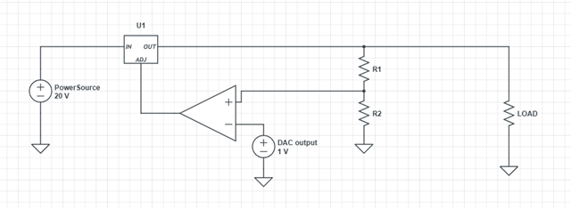
  2. Can the feedback pin be safely modulated or influenced via an op-amp circuit driven by the DAC (e.g., by injecting a voltage or modifying the feedback network)?

  3. If LM2596 is not suitable, could you suggest an alternative TI buck regulator that:

    • Supports DAC-adjustable output

    • Can work with 5V–24V input

    • Has ~1A output capability

    • Preferably doesn’t require I²C/SPI digital interface (just analog control)

I'm open to a discrete circuit around a controller IC if needed. Just trying to avoid digital-controlled PMICs and keep it analog + DAC.

Thanks in advance for any advice!

  • Hi,

    Technically speaking, it may be possible to modulate your output voltage with a signal on FB. The biggest issue I see however is your inductor current ripple would vary wildly, and care will need to be taken to ensure that you are not putting your device into an unstable condition.

    Can you please share a block diagram of what you are attempting to accomplish? 

    Thank you,

    Joshua Austria

  • hi joshua,

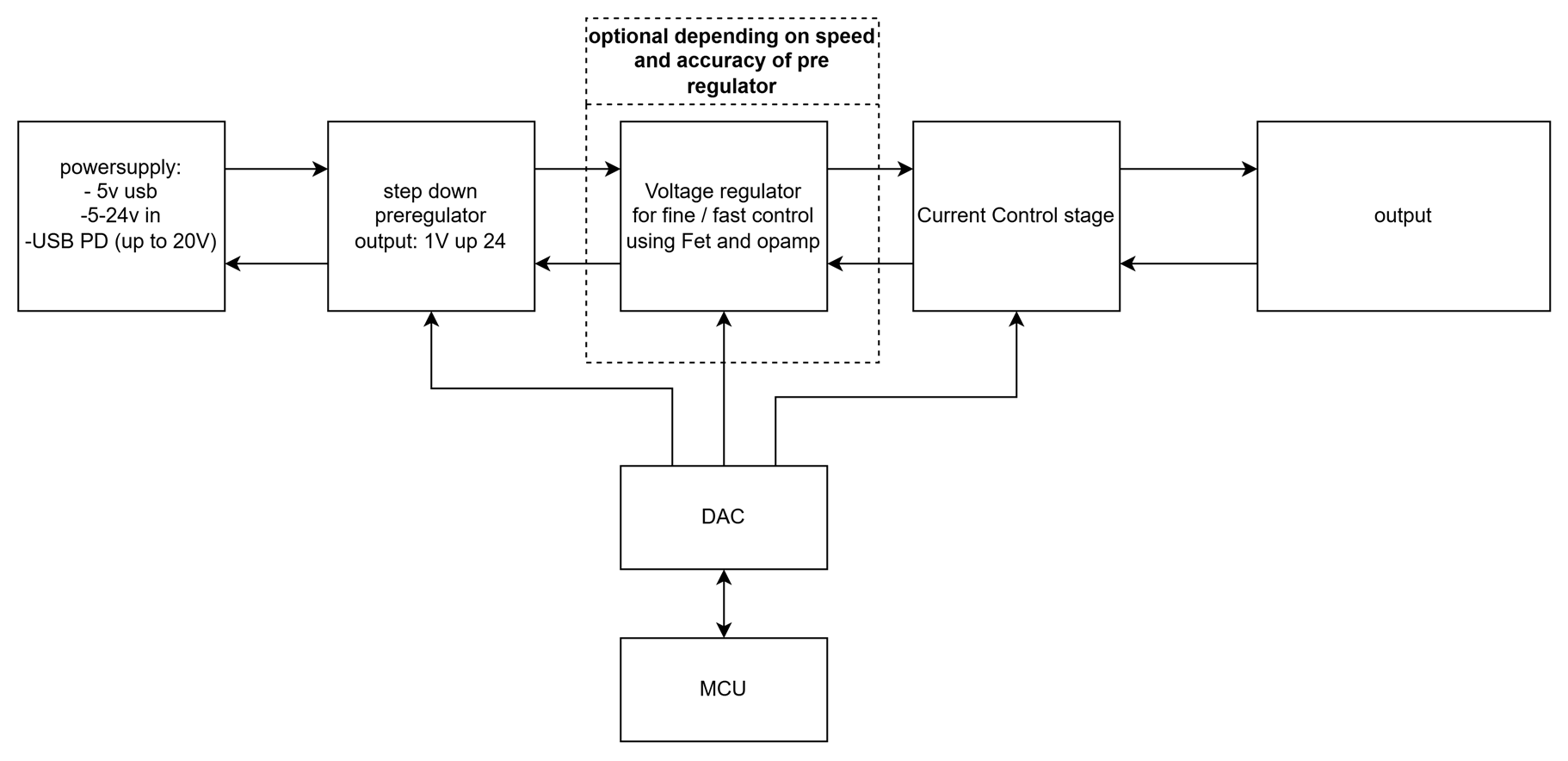
     this is the block diagram of the system i want to create. 
    the goal is to make a mcu controllable current and voltage supply that can be used to test embedded systems. the system will also allow to measure the voltage and current at the output so you can do things like powerprofiling of low power stuff. the reason for the current supply is that i also want to be able to do things like testing LED's. 

    the part i want to use the buck converter for is the step down preregulator. since i dont want to choke all power through a FET. 

  • according to Reddit something like this could also work. can you confirm this? also if you would suggest some other buck converter that is totally fine. as long as it can meet my specs and is not very expensive it's oke.


  • Hi Thomas,

    Is this circuit essentially modulating the voltage that the feedback pin receives? This could also be doable with a circuit that modulates either the R1 or R2 resistors such that the setpoint for VOUT varies. 

    As long as the feedback pin voltage is not forced past its absolute maximum rating of 25V, this should be ok. Please keep in mind however the caveats as noted previously.

    Also please ensure that you are utilizing the adjustable output voltage versions of this device. 

    Thank you,

    Joshua Austria

  • Hi Thomas,

    Was there a reason that this thread was reopened?

    If so, please provide details on your next inquiry and feel free to reopen the thread.

    Thank you,

    Joshua Austria